IAI America MSEP User Manual
Page 85
3.2 Initial Setting
77
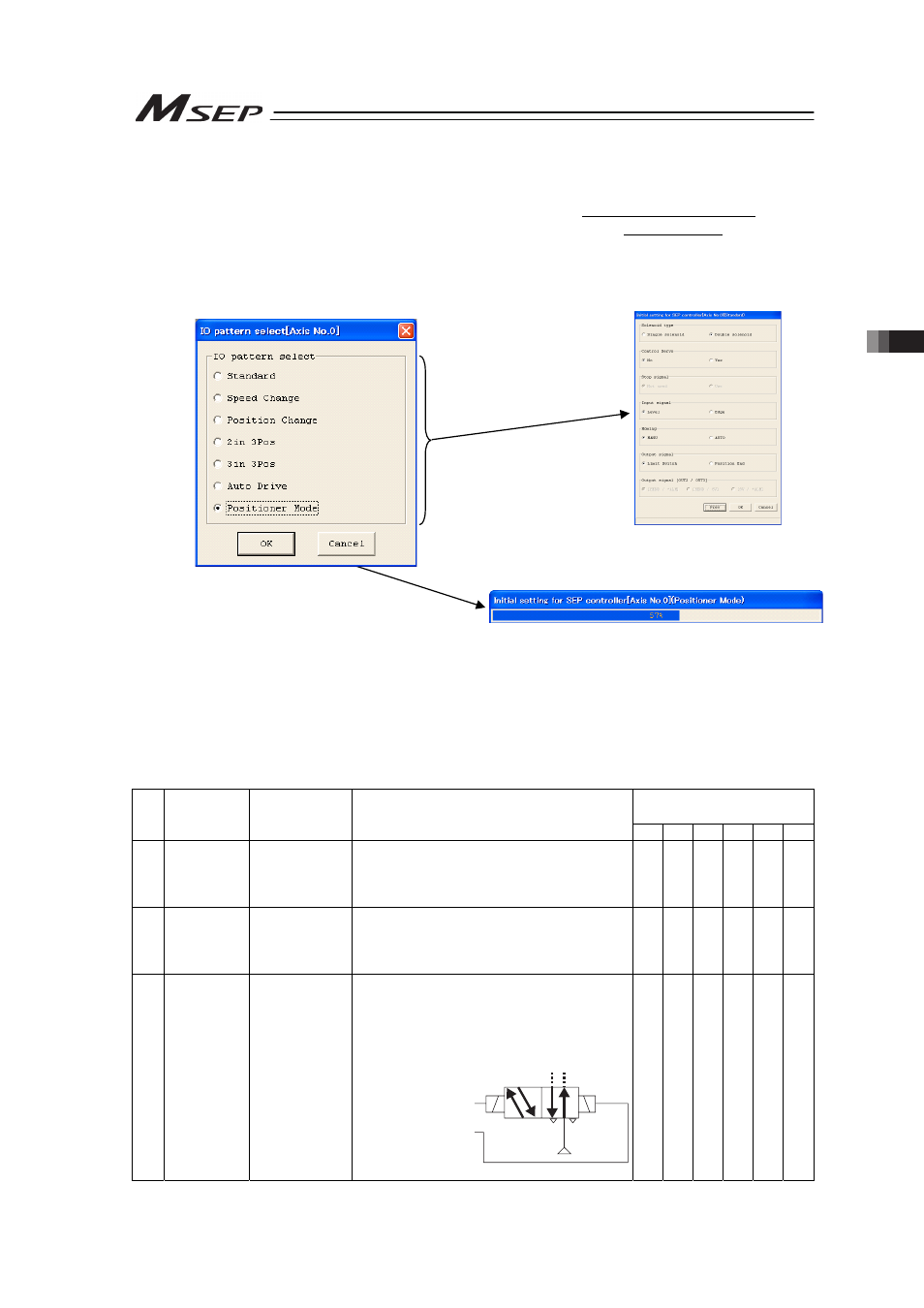
[Step 4] Select the operation pattern.
There are Operation Patterns 0 to 5 available for PIO Type.
Select Operation Pattern 6 if Fieldbus Type and a mode other than SEP I/O Mode.
Select either of Operation Patterns 0 to 5 if Fieldbus Type and SEP I/O Mode since control
is the same as PIO Type.
By pressing OK after the selection is made, the display proceeds to the next step for
Operation Patterns 0 to 5, and the initial setting data is sent to the controller for Operation
Pattern 6.
[Step 5] (Note) For Operation Pattern 6, proceed to Step 7.
If the operation pattern is either of 0 to 5, have the following setting. The items to set vary
depending on the operation pattern you have chosen, and will be some items that are not
shown.
Set the displayed item and click on OK button.
Statement in a bracket is the setting at the delivery.
Operation Pattern
({ : Available for Setting)
No. Setting Item Setting Range
(Set in delivery)
Description
0
1
2
3
4
5
1 Solenoid
System
Single/Double
(Double)
Single : Actuator is operated with a control
same as Single Solenoid.
Double : Actuator is operated with a control
same as Double Solenoid System.
{
{
{
2 Stop Signal Use/
Not to Use
(Not to Use)
This is available only if Single is selected in
No.1.
When the PAUSE signal (*STP) is used,
select “Use”.
{
{
{
{
3 Input Signal
System
Continuous
Operation Type
/Momentary
Operation Type
(Continuous
Operation
Type)
This is available only if Double is selected in
No.1.
For the signal sent from PLC to MSEP, select
“Continuous Operation” (level signal) or
“Momentary Operation” (edge signal).
(Reference) Double Solenoid Circuit
A
B
R1
R2
Solenoid B
T
T
Solenoid A
Solenoid A Control Signal
Solenoid B Control Signal
P (Air)
{
{
{
{
For Operation Pattern 6
For Operation Pattern 0 to 5
[Refer to Step 5 for the details]