8 i/o signal controls and function – IAI America MSEP User Manual
Page 158
3.8 I/O Signal Controls and Function
150
3.8 I/O Signal Controls and Function
3.8.1
Input and Output Signal for Fieldbus Type (except for SEP I/O Mode)
This section explains the signals except for SEP I/O Mode and PIO Operation of Fieldbus Type.
In Fieldbus Type, the applicable bit is “1” when the signal is ON and “0” when it is OFF.
(1) Controller ready (CRDY) PLC Input Signal
When the controller can control the system after the power injection, it is turned “ON”.
Ŷ Function
Regardless of the alarm or servo conditions, when the controller initialization is completed
normally after the power injection and the controller can control the system, it is turned “ON”.
Even in the alarm condition, when the controller can control the system, it is turned “ON”.
(2) Emergency stop (EMGS) PLC Input Signal
When the controller is stopped in an emergency, it is turned “ON”.
Ŷ Function
When the controller is stopped in an emergency (motor driving power is cut off), it is turned
“ON”. When the emergency stop status is cleared, it is turned “OFF”.
(3) Alarm (ALM) PLC Input Signal
When any error is detected using the controller protection circuit (function), it is turned “ON”.
Ŷ Function
When any error is detected and the protection circuit (function) is activated, this signal is turned
“ON”.
When the cause of the alarm is eliminated and the reset (RES) signal is turned “ON”, the alarm
is turned “OFF” in the case that it is the alarm with the operation cancellation level. (In the case
of the alarm with the cold start level, re-injection of the power is required.)
(4) Reset (RES) PLC Output Signal
This signal has two functions. It can reset the controller alarm and cancel the reminder for
planned movements during pause conditions.
Ŷ Function
1) When this signal is turned ON from OFF condition after eliminating the cause of the alarm
during the alarm output, the alarm (ALM) signal can be reset. (In the case of the alarm with
the cold start level, re-injection of the power is required.)
2) When this signal is turned ON from OFF condition during the pause condition, the reminder
of the planned movement left can be cancelled.
(5) Servo ON command (SON) PLC Output Signal
Operation ready (SV)
PLC Input Signal
When the SON signal is turned ON, the servo will turn ON.
When the servo-motor is turned ON, the Status Indicator LED (SYS*) on the front surface of the
controller illuminates in green.
The “SV” signal is synchronized with this LED.
Ŷ Function
Using the “SON” signal, the turning ON/OFF of the controller is available.
While the “SV” signal is ON, the controller's servo-motor is turned “ON” and the operation
becomes available.
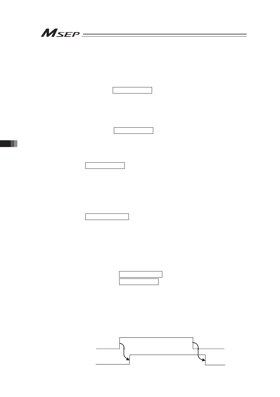
The relationship between the “SON” signal and “SV” signal is as follows.
SON
(PLC → MSEP)
SV
(MSEP → PLC)