IAI America MSEP User Manual
Page 101
3.4 Fieldbus
Type
Address Map
93
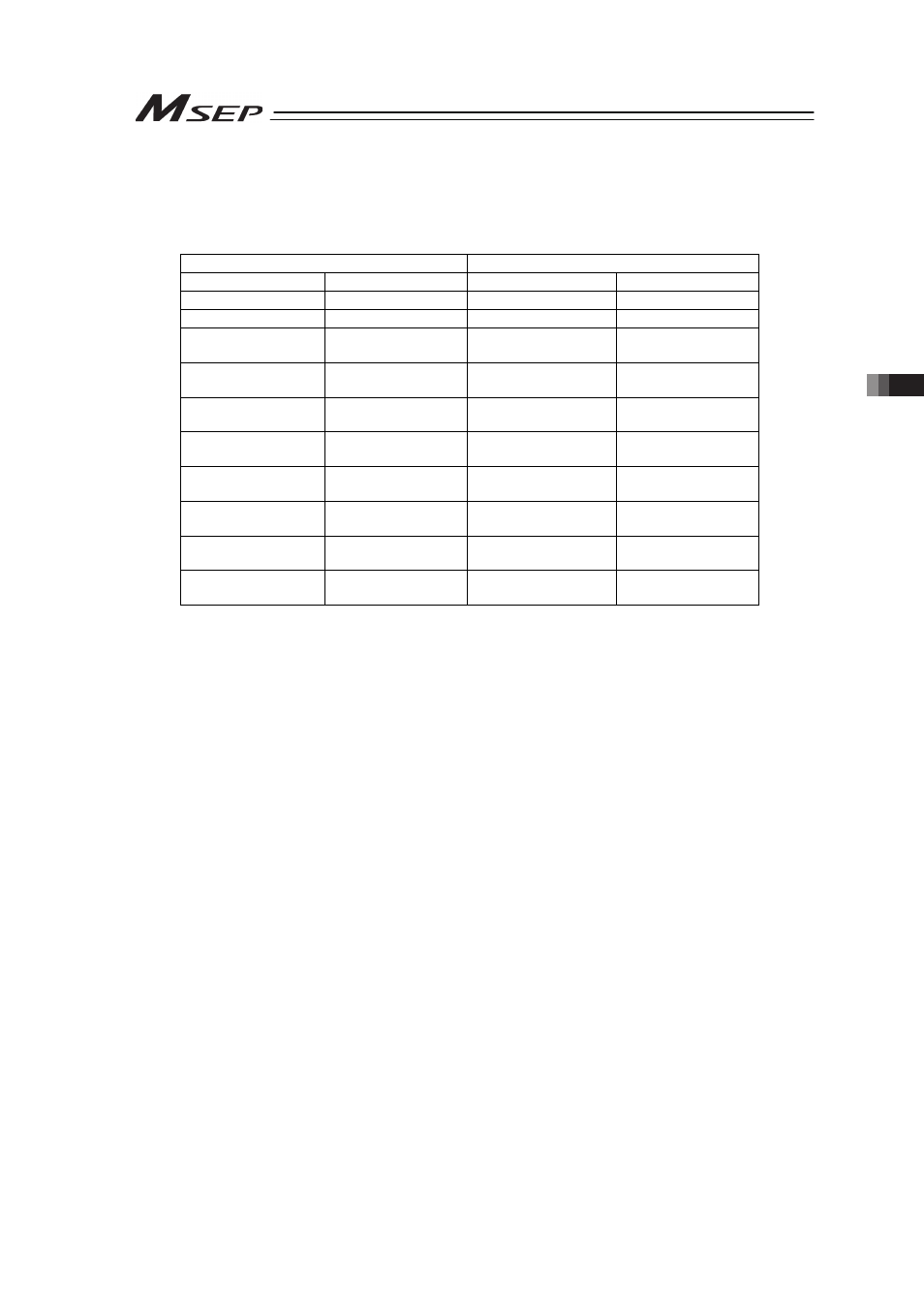
1) DeviceNet (CompoNet is not applicable for this mode)
[Combination Example 1] When number of Simple Direct Mode axes is 8 and number of
Direct Indication Mode 0
(n is the top channel number for each PLC input and output
between MSEP and PLC)
PLC ĺ MSEP
MSEP ĺ PLC
CH No.
Description
CH No.
Description
n to n+1
Gateway Control
n to n+1
Gateway Status
n+2 to n+7
Demand Command
n+2 to n+7
Response Command
n+8 to n+11
Axis No.0 Control
Information
n+8 to n+11
Axis No.0 Status
Information
n+12 to n+15
Axis No.1 Control
Information
n+12 to n+15
Axis No.1 Status
Information
n+16 to n+19
Axis No.2 Control
Information
n+16 to n+19
Axis No.2 Status
Information
n+20 to n+23
Axis No.3 Control
Information
n+20 to n+23
Axis No.3 Status
Information
n+24 to n+27
Axis No.4 Control
Information
n+24 to n+27
Axis No.4 Status
Information
n+28 to n+31
Axis No.5 Control
Information
n+28 to n+31
Axis No.5 Status
Information
n+32 to n+35
Axis No.6 Control
Information
n+32 to n+35
Axis No.6 Status
Information
n+36 to n+39
Axis No.7 Control
Information
n+36 to n+39
Axis No.7 Status
Information