IAI America MSEP User Manual
Page 136
3.4 Fieldbus
Type
Address Map
128
3.4.9
About Commands (Position Data Read/Write and Alarm Axis Read)
By sending a specific code to a specific address, the position data reading and writing, and the
reading of the axis number that an alarm was issued and the alarm code can be performed.
(Note) It is not necessary to use commands in Simple Indication Mode because no position
data is to be used in it.
Caution:
• The command cannot be used in MECHATROLINK.
• It is not necessary to use commands in Simple Direct Mode because no position data is to
be used in it.
Shown below is the table to indicate the assignment of each signal.
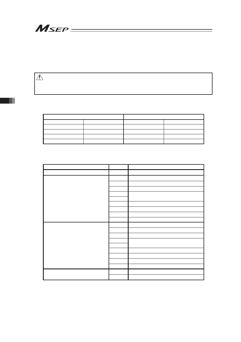
(1) PLC Address Composition
(n is PLC input and output top address.)
PLC ĺ MSEP (PLC Output)
MSEP ĺ PLC (PLC Input)
Demand Command
n+2
Response Command
n+2
Data 0
n+3
Data 0
n+3
Data 1
n+4
Data 1
n+4
Data 2
n+5
Data 2
n+5
Data 3
n+6
Data 3
n+6
[Refer to Section 3.4.2 for the address maps for each Fieldbus.]
䎃
(2) Demand Command List
Class
Code
Description
Handshaking
0000
H
Demand command cleared
Write Position Data
1000
H
Writing of target position
1001
H
Writing of pressing width
1002
H
Writing of speed
1003
H
1004
H
Cannot be used.
1005
H
Writing of acceleration
1006
H
Writing of deceleration
1007
H
Writing current limit at pressing
1008
H
Cannot be used.
Read Position Data
1040
H
Reading of target position
1041
H
Reading of pressing width
1042
H
Reading of speed
1043
H
1044
H
Cannot be used.
1045
H
Reading of acceleration
1046
H
Reading of deceleration
1047
H
Reading of current limit at pressing
1048
H
Cannot be used.
Error Information Monitoring
4000
H
Error Information Monitoring
4001
H
Acquiring alarm-issued axis