IAI America MSEP User Manual
Page 23
15
12) Status LED
They are the LED lamps to show the status of the controller and PIO or Fieldbus.
The layout and the content of LED display differ depending on PIO or each Fieldbus.
Refer to the operation of each mode for the details.
[Refer to 3.10 Status LEDs.]
13) Fieldbus/PIO Connector
A connector for Fieldbus connection is mounted for the Fieldbus. Type while PIO connector
is equipped for PIO Type.
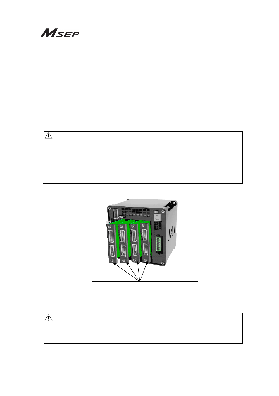
14) to 17) Slot 0 to 3 Actuator Connector
Insert one driver board to one slot each. (Four driver boards are available to insert at the
maximum.)
Each driver board can control two axes.
Caution : (1) There are two types of driver board, one is for the pulse motor and the other
for the 24V servo motor, and each board is available for the connection of
different actuators.
(2) Do not attempt to insert the driver board to a slot other than the one that the
board was originally inserted to.
The parameter dedicated for the indicated actuator is already written to the
driver board at the purchase order. Inserting the driver board to another slot
may lead to a wrong wiring.
(3) On the slot without a driver board inserted, there is a face plate attached.
Caution : Cutoff/boot of driving source is to be done on each driver board (2 axes) (control
by one axis to another cannot be performed). Therefore, when Cold Start Level
(Drive Cutoff) Alarm is generated on one axis out of two, the other axis with the
alarm not being generated will also stop. Consider this when constructing the
system.
Driver Board
For pulse motor or 24V servo motor
(to be indicated at the purchase order considering
the connected actuator type)