3 circuit diagram, Power supply and emergency stop, Chapter 2 wiring – IAI America MSEP User Manual
Page 50: Sample circuit diagrams are shown below
Chapter 2 Wiring
42
2.3 Circuit Diagram
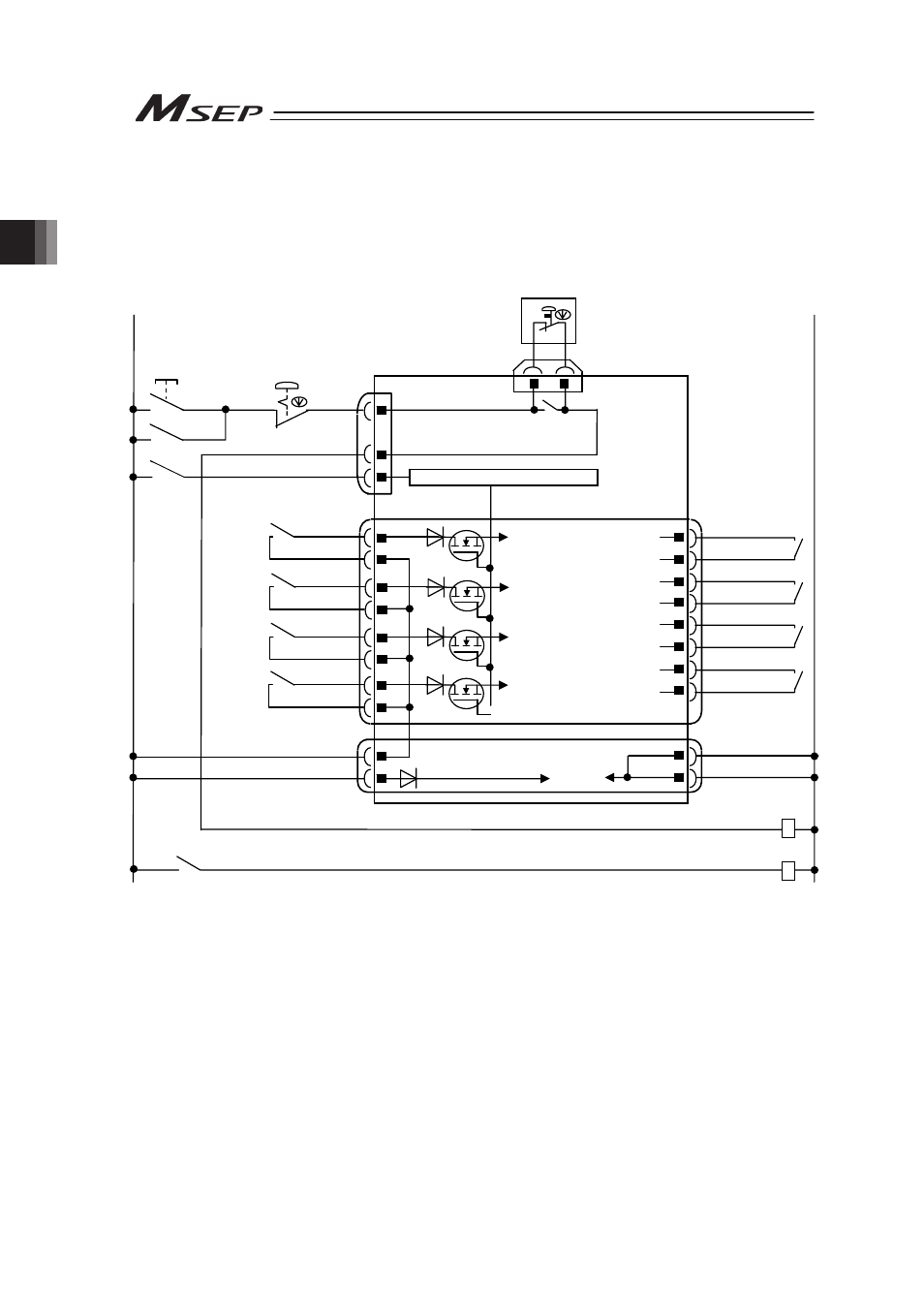
Sample circuit diagrams are shown below.
[1]
Power Supply and Emergency Stop
The diagram shown below is an example of a circuit for when reflecting the emergency stop
switch on a teaching pendant to the emergency stop circuit of the system.
Note 1 When the teaching pendant is not connected, S1 and S2 become short-circuited inside the controller.
Note 2 When the motor power must be disconnected externally for safety category compliance, apply a safety rated
contactor between MPISLOT* and MPOSLOT*. Choose one that is capable to open and close with the motor
current consumption of the connected actuator [Refer to 1.2 List of Basic Specifications.].
Note 3 The rating for the emergency stop signal (EMG-) to turn ON/OFF at contact CR1 is 24V DC and 10mA.
Note 4 For CR1, select the one with coil current 0.1A or less.
Note 5 If supplying power with using a 24V DC, having it turned ON/OFF, keep the 0V connected and have the +24V
supplied/cut (cut one side only).
Note 6 By cutting out the connection between EMG+SLOT* and EMGINSLOT*, only the disconnected slot number can be
made in the condition of an emergency stop. (*: Slot Number)
EMGINSLOT0
EMGINSLOT1
EMGINSLOT2
EMGINSLOT3
Emergency Stop
Reset Switch
Emergency Stop
Switch
CR1
SIO Connector
CR1
24V
0V
Emergency Stop Control Circuit
Motor Power Supply (Slot 3)
(Axis No.6 and 7)
MPISLOT3
MPOSLOT3
CR2
(Note 2)
MPISLOT2
MPOSLOT2
CR2
(Note 2)
MPOSLOT1
MPISLOT1
CR2
(Note 2)
MPISLOT0
MPOSLOT0
CR2
(Note 2)
Motor Power Supply (Slot 2)
(Axis No.4 and 5)
Motor Power Supply (Slot 1)
(Axis No.2 and 3)
Motor Power Supply (Slot 0)
(Axis No.0 and 1)
MP+24V
0V
CP+24V
0V
Control
Power
External Drive Cutoff •
Emergency Stop Input Connector
Power Line Input Connector
EMG+SLOT0
(Note 6)
S1
4
3
2
1
12
11
10
9
7
8
5
6
15
16
13
14
1
3
4
2
Emergency Stop Switch on
Teaching Pendant
S2
(Note1)
EMG A
EMG B
MSEP
8
5
EMG-
EMG+SLOT1
(Note 6)
EMG+SLOT2
(Note 6)
EMG+SLOT3
(Note 6)
3
2
4
CR1
(Note 4)
CR2
(Note 2)
CR1
System I/O Connector