5 control signals for pio operation, I/o signal assignment – IAI America MSEP User Manual
Page 152
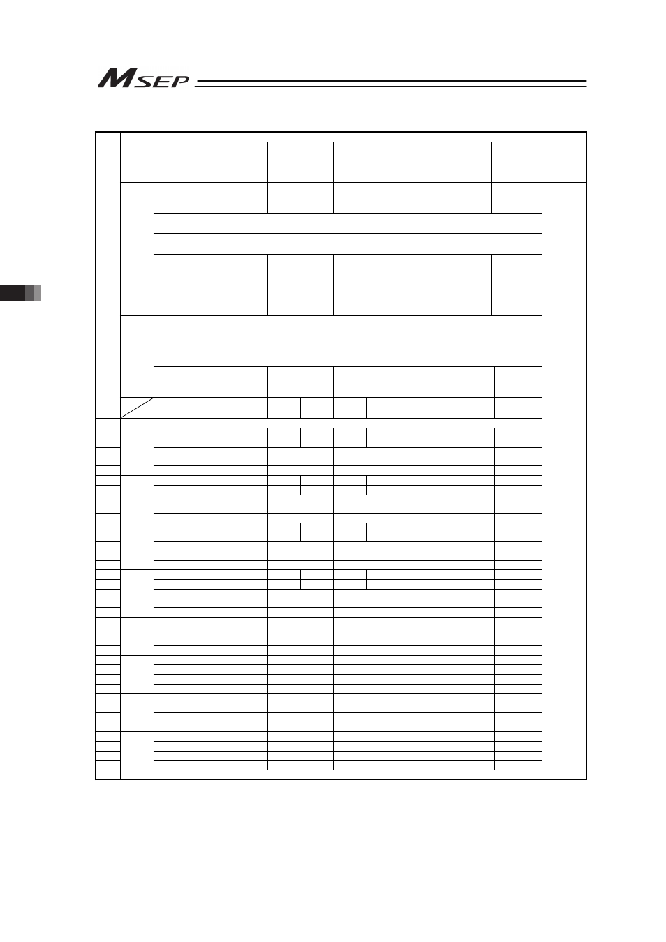
3.5 Control Signals for PIO Operation
144
I/O signal assignment
Operation Pattern (PIO pattern)
0
1
2
3
4
5
Category
PIO
Functions
Point-to-Point
Movement
Movement speed
setting
Target position
change
2-Input,
3-Point
Movement
3-Input,
3-Point
Movement
Continuous
reciprocating
operation
Fieldbus
connection
Number of
positioning
points
2 points
2 points
2 points
3 points
3 points
2 points
Home return
signal
× (Home-return operation at the power-on or the first movement operation)
Servo ON
signal
ż (Automatic servo-on is also available at the power-on)
Movement
speed
setting
×
ż
Ч
Ч
Ч
Ч
Input
Target
position
change
Ч
Ч
ż
Ч
Ч
Ч
Servo ON
signal
ż (Selection available in the initial setting whether to use)
Homing
completion
signal
ż (Selection available in the initial setting whether to
use)
×
ż (Selection available in
the initial setting
whether to use)
Output
Zone signal,
Position
zone sig
Ч
Ч
Ч
Ч
Ч
Ч
Pin
No.
Solenoid
system
Single Double Single Double Single Double
–
Double
–
A1
–
COM
24V
A2
IN0
ST0
ST0
ST0
ST0
ST0
ST0
ST0
ST0
ASTR
A3
IN1
*STP ST1
(Note 1)
*STP ST1
(Note 1)
*STP ST1
(Note 1)
ST1
(Note 1)
ST1
(Note 1)
*STP
A4
IN2
RES
SPDC(RES)
(Note 2)
CN1(RES)
(Note 2)
RES
ST2(RES)
(Note 2)
RES
A5
Input
(Axis
No.0)
IN3
–/SON
–/SON
–/SON
–/SON
–/SON
–/SON
A6
IN0
ST0
ST0
ST0
ST0
ST0
ST0
ST0
ST0
ASTR
A7
IN1
*STP ST1
(Note 1)
*STP ST1
(Note 1)
*STP ST1
(Note 1)
ST1
(Note 1)
ST1
(Note 1)
*STP
A8
IN2
RES
SPDC(RES)
(Note 2)
CN1(RES)
(Note 2)
RES
ST2(RES)
(Note 2)
RES
A9
Input
(Axis
No.1)
IN3
–/SON
–/SON
–/SON
–/SON
–/SON
–/SON
A10
IN0
ST0
ST0
ST0
ST0
ST0
ST0
ST0
ST0
ASTR
A11
IN1
*STP ST1
(Note 1)
*STP ST1
(Note 1)
*STP ST1
(Note 1)
ST1
(Note 1)
ST1
(Note 1)
*STP
A12
IN2
RES
SPDC(RES)
(Note 2)
CN1(RES)
(Note 2)
RES
ST2(RES)
(Note 2)
RES
A13
Input
(Axis
No.2)
IN3
–/SON
–/SON
–/SON
–/SON
–/SON
–/SON
A14
IN0
ST0
ST0
ST0
ST0
ST0
ST0
ST0
ST0
ASTR
A15
IN1
*STP ST1
(Note 1)
*STP ST1
(Note 1)
*STP ST1
(Note 1)
ST1
(Note 1)
ST1
(Note 1)
*STP
A16
IN2
RES
SPDC(RES)
(Note 2)
CN1(RES)
(Note 2)
RES
ST2(RES)
(Note 2)
RES
A17
Input
(Axis
No.3)
IN3
–/SON
–/SON
–/SON
–/SON
–/SON
–/SON
A18
OUT0
LS0/PE0
LS0/PE0
LS0/PE0
LS0/PE0
LS0/PE0
LS0/PE0
A19
OUT1
LS1/PE1
LS1/PE1
LS1/PE1
LS1/PE1
LS1/PE1
LS1/PE1
A20
OUT2
HEND/SV
HEND/SV
HEND/SV
LS2/PE2
LS2/PE2
HEND/SV
A21
Output
(Axis
No.0)
OUT3
*ALM/SV
*ALM/SV
*ALM/SV
*ALM/SV
*ALM/SV
*ALM/SV
A22
OUT0
LS0/PE0
LS0/PE0
LS0/PE0
LS0/PE0
LS0/PE0
LS0/PE0
A23
OUT1
LS1/PE1
LS1/PE1
LS1/PE1
LS1/PE1
LS1/PE1
LS1/PE1
A24
OUT2
HEND/SV
HEND/SV
HEND/SV
HEND/SV
LS2/PE2
LS2/PE2
A25
Output
(Axis
No.1)
OUT3
*ALM/SV
*ALM/SV
*ALM/SV
*ALM/SV
*ALM/SV
*ALM/SV
A26
OUT0
LS0/PE0
LS0/PE0
LS0/PE0
LS0/PE0
LS0/PE0
LS0/PE0
A27
OUT1
LS1/PE1
LS1/PE1
LS1/PE1
LS1/PE1
LS1/PE1
LS1/PE1
A28
OUT2
HEND/SV
HEND/SV
HEND/SV
HEND/SV
LS2/PE2
LS2/PE2
A29
Output
(Axis
No.2)
OUT3
*ALM/SV
*ALM/SV
*ALM/SV
*ALM/SV
*ALM/SV
*ALM/SV
A30
OUT0
LS0/PE0
LS0/PE0
LS0/PE0
LS0/PE0
LS0/PE0
LS0/PE0
A31
OUT1
LS1/PE1
LS1/PE1
LS1/PE1
LS1/PE1
LS1/PE1
LS1/PE1
A32
OUT2
HEND/SV
HEND/SV
HEND/SV
HEND/SV
LS2/PE2
LS2/PE2
A33
Output
(Axis
No.3)
OUT3
*ALM/SV
*ALM/SV
*ALM/SV
*ALM/SV
*ALM/SV
*ALM/SV
Refer to 3.4
Fieldbus
Type
Address
Map
A34
–
COM
0V
(Note) “*” in codes above shows the signal of the active low.
(Note 1) It is invalid before home-return operation.
(Note 2) The description in the brackets shows the condition before the home return operation.