Chapter 4 absolute reset and absolute battery, 1 absolute reset, 1] status leds for driver – IAI America MSEP User Manual
Page 203
Chapter 4
Absolute Reset and
Absolute Battery
195
Chapter 4 Absolute Reset and Absolute Battery
4.1 Absolute Reset
The controller for Simple Absolute Type retains the encoder position information with the
battery backup. It is not necessary to perform the home-return operation every time the power
is turned ON.
In order to hold the encoder position information, absolute reset is required.
It can be checked on the status LEDs for the driver whether the absolute reset is necessary.
Have an absolute reset completed if the status LEDs for the driver shows the absolute reset is
incomplete.
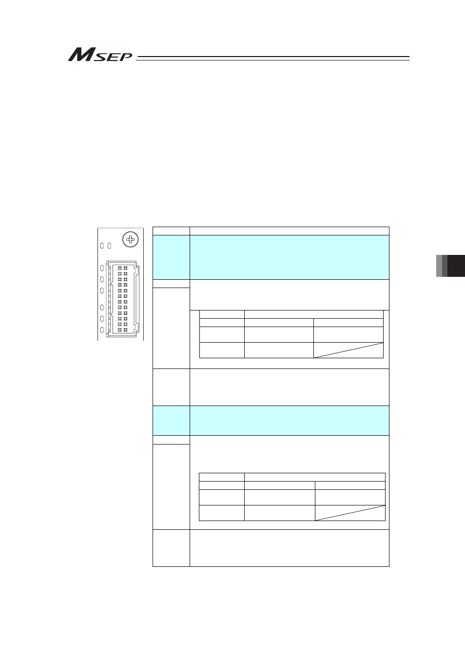
[1] Status LEDs for Driver
These lamps indicate the status of the driver and that for absolute type for each slot (in 2
axes unit). There is no absolute status display for the incremental type.
Name
Description
SYS I
Driver for upper connector connection axes numbers (0, 2, 4 and 6
Axis)
System status
Green Light is turned ON. : Servo ON
Red Light is turned ON. : Alarm generated
OFF : Servo OFF
I–0
Absolute Status 1 for driver for upper connector connection axes
numbers (0, 2, 4 and 6 Axis)
The current absolute status is expressed of the patterns of the light in
I-0 and I-1.
I–1
I–0
Green Light is turned ON. Red Light is turned ON.
Green Light is
turned ON.
Absolute reset complete Absolute reset
incomplete
Red Light is
turned ON.
Alarm generated
I–1
I–2
Absolute Status 2 for driver for upper connector connection axes
numbers (0, 2, 4 and 6 Axis)
Green Light is turned ON. : Battery fully charged
Orange Light is turned ON. : Battery charging operation
Red Light is turned ON. : Battery disconnected
SYS II
Driver for lower connector connection axes numbers (1, 3, 5 and 7 Axis)
Green Light is turned ON. : Servo ON
Red Light is turned ON. : Alarm generated
OFF : Servo OFF
II–0
Absolute Status 1 for driver for lower connector connection axes
numbers (1, 3, 5 and 7 Axis)
The current absolute status is expressed of the patterns of the light in II
II-0 and II-1.
II–1
II–0
Green Light is turned ON. Red Light is turned ON.
Green Light is
turned ON.
Absolute reset complete Absolute reset
incomplete
Red Light is
turned ON.
Alarm generated
II–1
SYS
I II
0
1
2
0
1
2
I
II
II–2
Absolute Status 2 for driver for lower connector connection axes
numbers (1, 3, 5 and 7 Axis)
Green Light is turned ON. : Battery fully charged
Orange Light is turned ON. : Battery charging operation
Red Light is turned ON. : Battery disconnected