3 calculation for power capacity – IAI America MSEP User Manual
Page 31
Chapter 1 Specifications Check
23
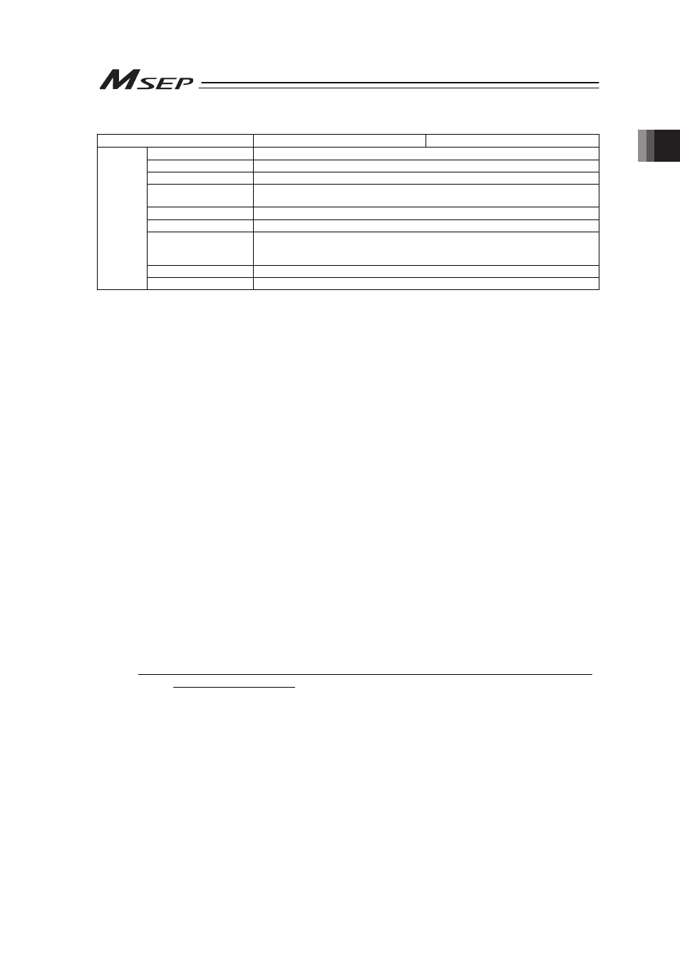
Specification Item
Driver for Servo Motor
Driver for Pulse Motor
Ambient Temperature
0 to 40qC
Ambient Humidity
85%RH or less (non-condensing)
Ambient Environment
[Refer to Installation Environment]
Ambient Storage
Temperature
-20 to 70qC (0 to 40qC for absolute battery)
Ambient Storage Humidity 85%RH or less (non-condensing)
Usable Altitude
1000m or lower above sea level
Vibration Durability
Frequency 10 to 57Hz / Swing width: 0.075mm
Frequency 57 to 150Hz / Acceleration: 9.8m/s
2
XYZ Each direction Sweep time: 10 min. Number of sweep: 10 times
Shock Resistance
150mm/s
2
11ms Semi-sine wave pulse three times to each of the directions X, Y and Z
Environment
Protection Class
IP20
Note 1 Maximum current draw is realized during the excitation phase following the initial servo power ON. (Normal: Approx.
1 to 2 sec, MAX: 10 sec).
Note 2 The current is maximized at the excitation phase detection conducted in the first servo-on process after the power is
supplied (ordinary 100ms). However, approximately 6A current flows at the recovery (when the drive power is
supplied) from an emergency stop (approx. 1 to 2ms).
Note 3 For servo motor, the over-current protection is triggered at 1.4 times the maximum load current.
Note 4 It is not applicable for the high output setting even if RCP4 is connected.
1.3 Calculation for Power Capacity
For the calculation of 24V DC power capacity, figure out the numbers for (1) to (6) below, and
then follow Step (7).
(1) Control Power Current Consumption : 0.8A ·······································································1)
(2) Motor Power Current Consumption :
Add the total motor current consumption of all connected actuators.·································2)
(3) Current Consumption at Excitation Phase Detection :
Add the inrush current for all connected axes. ···································································3)
(4) Add the Control Power Inrush Current : Number of slots × 5A each. ·································4)
(5) Add the Motor Power Inrush Current : Number of slots × 10A each. ·································5)
(6) Current consumption of brake power supply : Number of actuators with brake × 0.15A····6)
(7) Selection of Power Supply :
Usually, the rated current is to be approximately 1.3 times higher than the total of Control
Power (1) and Motor Power (2) and brake power (6) above considering approximately 30%
of margin to the load current. However, considering the inrush currents [excitation (3),
control (4) and motor power (5)], even though it is a short time, select a power supply with
“sufficient peak load capacity. High cumulative inrush currents can be avoided by taking
precautions to phase the initial servo ON condition and e-stop recovery so that they occur
at different times. If a power supply with insufficient peak capacity is utilized, voltage
drooping may occur. This may present issues with power supplies providing remote sensing
functionality.
(Note) Ensure motor and control power supplies reference the same potential when using
multiple power supplies.
(Reference) Selection of Power Supply Protection Circuit Breaker
It is recommended that the power supply protection is conducted on the primary side (AC
power side) of the 24V DC power supply unit.
When selecting the protection breaker, consider the rated cutoff current of the circuit breaker so
a cutoff is surely performed even in the case of inrush current of 24V DC power supply unit or a
short-circuit of the power supply.
• Rated Breaking Current > Short-circuit Current = Primary Power Supply Capacity/Power
Voltage
• (Reference) In-rush Current of IAI Power Supply Unit PS241 = 50 to 60A, 3msec