2 operation pattern selected, 1 outline for operation patterns, Chapter 2 wiring – IAI America MSEP User Manual
Page 46
Chapter 2 Wiring
38
2.2 Operation Pattern Selected
2.2.1
Outline for Operation Patterns
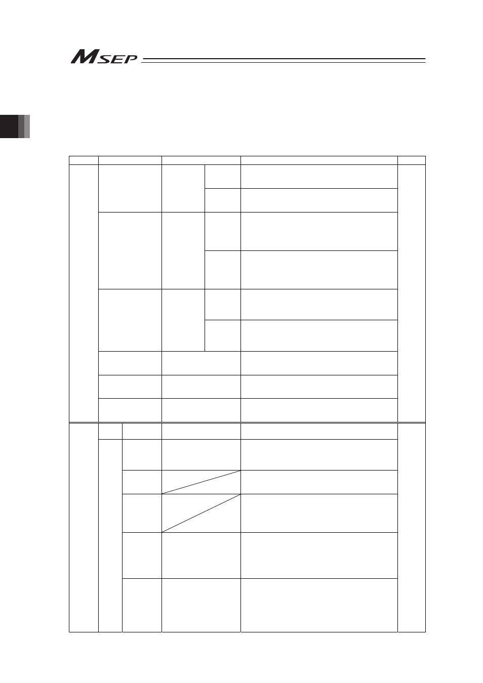
PIO type MSEP units provide 6 varying patterns of PIO operation. Fieldbus type MSEP units
provide 6 varying modes of fieldbus operation. Select an appropriate pattern or fieldbus mode
based upon your application requirements. See Section 3 Operation for the details of the
operation patterns.
Interface Operation Pattern Number of position points
Description
Details
Single
Solenoid
System
Control is performed with one input signal as it is done
for the single solenoid.
0 : Point-to-Point
Movement
2
(Forward end,
Backward
end)
Double
Solenoid
System
Control is performed with two input signals as it is
done for the double solenoid.
Single
Solenoid
System
Speed is available to change during a movement.
Control is performed with one input signal as it is done
for Single Solenoid, however, the speed can be
changed while in move if a movement speed change
signal is input.
1 : Point-to-Point
Movement,
Movement Speed
Setting
2
(Forward end,
Backward
end)
Double
Solenoid
System
Speed is available to change during a movement.
Control is performed with two input signals as it is
done for Double Solenoid, however, the speed can be
changed while in move if a movement speed change
signal is input.
Single
Solenoid
System
Control is performed with one input signal as it is done
for Single Solenoid, however, the target position and
operational condition can be changed while in move if
a target position change signal is input.
2 : Point-to-Point
Movement, Target
Position Change
2
(Forward end,
Backward
end)
Double
Solenoid
System
Control is performed with two input signals as it is
done for Double Solenoid, however, the target position
and operational condition can be changed while in
move if a target position change signal is input.
3 : 2-Input, 3-Point
Movement
3
(Forward end, Backward
end, Intermediate)
Movement is made among three points with the
combination of two input signals.
4 : 3-Input, 3-Point
Movement
3
(Forward end, Backward
end, Intermediate)
Movement is made among three points with three
input signals.
PIO
Type
5 : Continuous
Reciprocating
Operation
2
(Forward end, Backward
end)
Movement is made between the forward end and
backward end repeatedly while one input signal is ON.
3.1.1 (1)
0 to 5 SEP I/O
2 or 3
The same control as PIO stated previously is available
if the interface is Fieldbus.
Positioner 1 256
The position data can be registered at 256 points at
the maximum and a stop can be made at the
registered points. Monitoring of the current position is
also available.
Simple
Direct
The target position can be indicated directly with
inputting a number. Monitoring of the current position
is also available.
Number of
direct
numerical
specification
The target position, speed acceleration/deceleration
and pressing current limit can be indicated with
inputting a number. Monitoring of not only the current
position, but also the current speed and indicated
current are available.
Positioner 2 256
The position data can be registered at 256 points at
the maximum and a stop can be made at the
registered points. The monitoring of the current
position is not available.
This mode is that the transferred data is reduced from
Positioner 1 Mode.
Fieldbus
Type
6
Positioner 3 256
The position data can be registered at 256 points at
the maximum and a stop can be made at the
registered points. The monitoring of the current
position is not available.
This mode is that the transferred data is reduced from
Positioner 2 Mode to control only the minimum signals
necessary only for the movement operation.
3.1.1 (2)