4] layout for external brake input circuit, 5] layout of regenerative resistor (option) – IAI America MSEP User Manual
Page 54
Chapter 2 Wiring
46
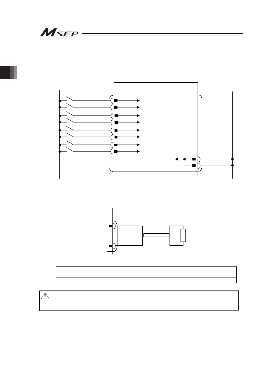
[4] Layout for External Brake Input Circuit
Lay out the circuit when an external compulsory brake release with using an actuator equipped
with a brake is desired. It is not necessary if an external release is not required.
It is possible to release the brake as long as the control power is supplied to MSEP even without
the main power being supplied to the controller.
[5] Layout of Regenerative Resistor (Option)
Condition to Require Regenerative Units
Number of Connected Actuator 3 to 8 units of high acceleration/deceleration type
actuators
Number of Regenerative Unit
1
Caution: The regenerative resistor consumes regenerative current and converts it to heat.
Therefore, the temperature may get high in some operational conditions.
Attach on the metal part of the device with a screw to radiate the heat.
Axis No.0 Brake Release Input Circuit
Axis No.7 Brake Release Input Circuit
Axis No.6 Brake Release Input Circuit
Axis No.4 Brake Release Input Circuit
Axis No.5 Brake Release Input Circuit
Axis No.3 Brake Release Input Circuit
Axis No.2 Brake Release Input Circuit
Axis No.1 Brake Release Input Circuit
MSEP
GND for Brake Release
BKRLS AXIS No.3
BKRLS AXIS No.0
BKRLS AXIS No.2
0V
0V
BKRLS AXIS No.5
BKRLS AXIS No.1
BKRLS AXIS No.4
BKRLS AXIS No.7
BKRLS AXIS No.6
24V
0V
External Brake Input Connector
MSEP
RB-
RB+
System I/O
Connector
External Regenerative
Resistor Units
(RER-1)
4
3
2
1
9
8
7
6
5
10
7
8