Chapter 7 appendix, 1 fan replacement – IAI America MSEP User Manual
Page 245
Chapter 7
Appendix
237
Chapter 7 Appendix
7.1 Fan Replacement
If an error is detected on the fan, replace the fan unit by following the process stated below.
Note 1: When there is an error on the fan, an alarm code will be output to the gateway status
signal or the gateway parameter setting tool.
Alarm Code
Alarm Name
48
Decrease in Fan Revolution
b7 to b0 in Gateway Status Signal 0
9E
Fun error
848
Decrease in Fan Revolution
Parameter Configuration tool
89E
Fun error
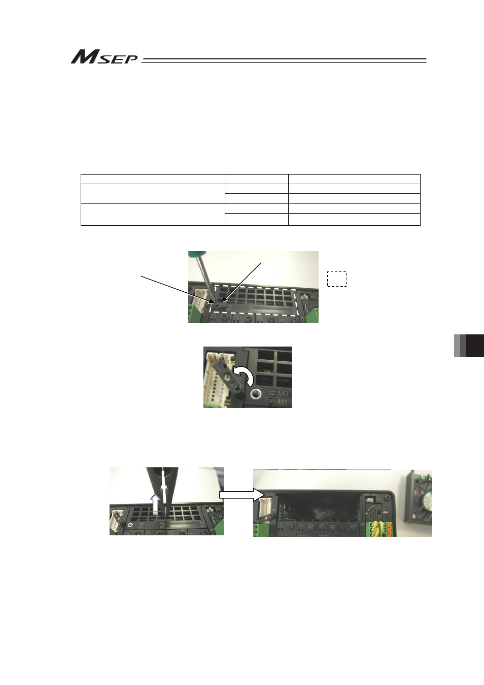
[Step 1] Prepare a new fan unit and remove the screw holding the fan unit.
[Step 2] Rotate the fan unit holder till it goes out of the fan unit interference.
[Step 3] Grab the lattice
*
on the fan unit with a tool such as needle-nose plier, and pull out the fan
unit.
*The lattice on the fan unit is disposable.
[Step 4] The new fan unit is to be pushed in to be settled. At this time, make sure the fan unit is
pushed in down to become flush with the peripheral.
[Step 5] Rotate the fan unit holder so the fan unit fixing screw can be tightened.
Fan unit holder
Fan unit fixing screw
Area: Fan Unit