8 connection of pio (for pio type), Chapter 2 wiring – IAI America MSEP User Manual
Page 71
Chapter 2 Wiring
63
2.4.8
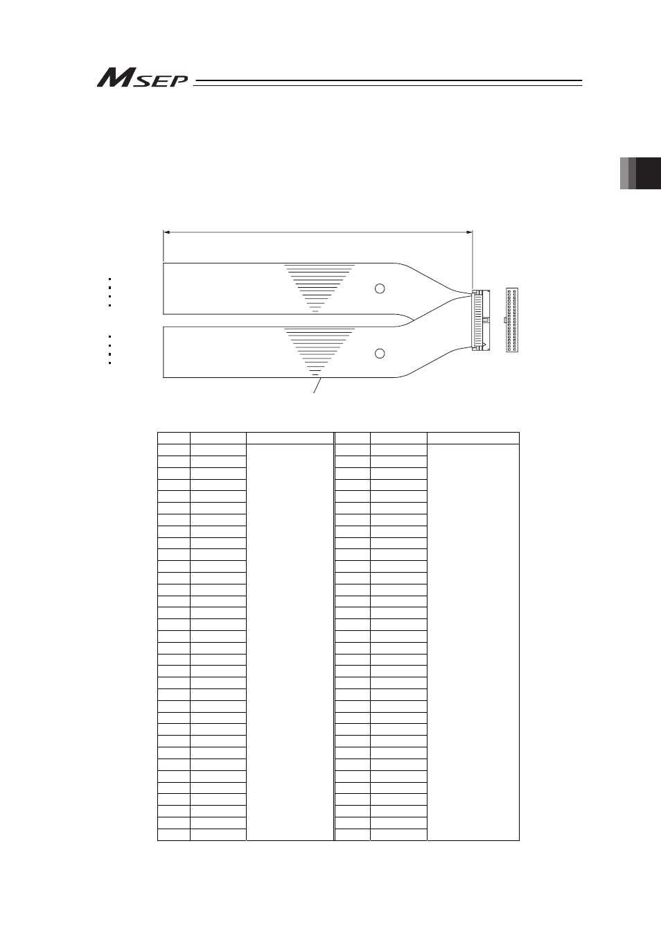
Connection of PIO (for PIO Type)
The connection of I/O to the controller is to be carried out using the dedicated I/O cable. The
cable length is shown in the model code of the controller. There are 2m for standard, 3m and
5m as an option. 10m is also applicable at maximum if purchased separately. [Refer to 1.1.5
How to read the model]
Also, the end of the cable harness to be connected to the host controller (PLC, etc.) is just cut
and no treatment is conducted so the wiring layout can be performed freely.
Model: CB-MSEP-PIOƑƑƑ (ƑƑƑ indicates the cable length L. Example. 020 = 2m)
Flat Cable (34-core) × 2
YW-8 (34B)
BR-5 (1B)
YW-4 (34A)
BR-1 (1A)
34A
34B
1A
1B
Half Pitch MIL Socket
HIF6-68D-1.27R (Hirose Electric)
A
B
L
No treatment
conducted
No treatment
conducted
No. Cable Color
Wiring
No.
Cable Color
Wiring
1A
BR-1
1B
BR-5
2A
RD-1
2B
RD-5
3A
OR-1
3B
OR-5
4A
YW-1
4B
YW-5
5A
GN-1
5B
GN-5
6A
BL-1
6B
BL-5
7A
PL-1
7B
PL-5
8A
GY-1
8B
GY-5
9A
WT-1
9B
WT-5
10A
BK-1
10B
BK-5
11A
BR-2
11B
BR-6
12A
RD-2
12B
RD-6
13A
OR-2
13B
OR-6
14A
YW-2
14B
YW-6
15A
GN-2
15B
GN-6
16A
BL-2
16B
BL-6
17A
PL-2
17B
PL-6
18A
GY-2
18B
GY-6
19A
WT-2
19B
WT-6
20A
BK-2
20B
BK-6
21A
BR-3
21B
BR-7
22A
RD-3
22B
RD-7
23A
OR-3
23B
OR-7
24A
YW-3
24B
YW-7
25A
GN-3
25B
GN-7
26A
BL-3
26B
BL-7
27A
PL-3
27B
PL-7
28A
GY-3
28B
GY-7
29A
WT-3
29B
WT-7
30A
BK-3
30B
BK-7
31A
BR-4
31B
BR-8
32A
RD-4
32B
RD-8
33A
OR-4
33B
OR-8
34A
YW-4
Flat Cable
ż
A
(Press Welding)
AWG28
34B
YW-8
Flat Cable
ż
B
(Press Welding)
AWG28