4 fieldbus type address map – IAI America MSEP User Manual
Page 117
3.4 Fieldbus
Type
Address Map
109
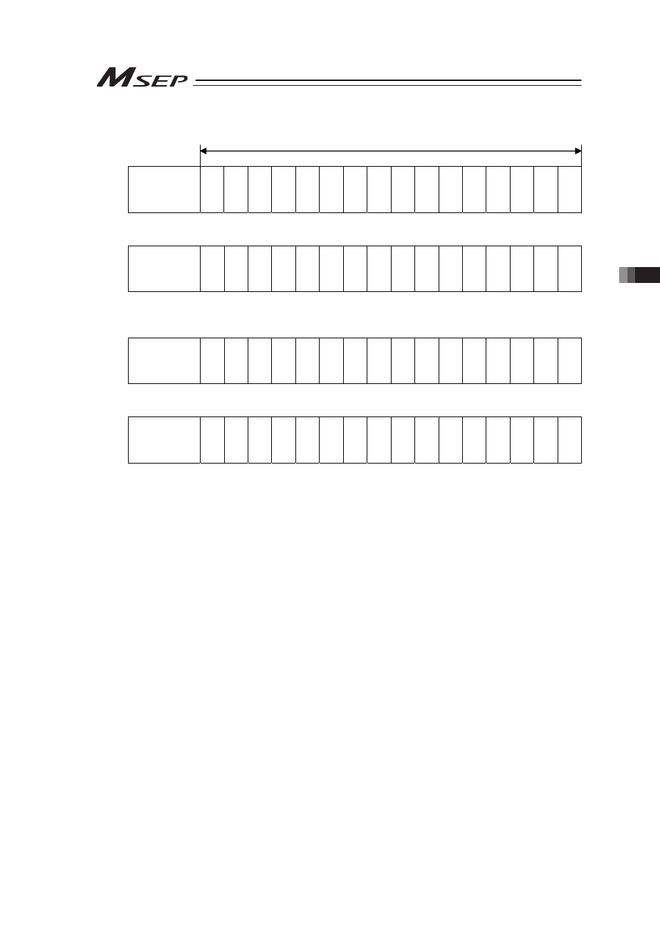
PLC Input (m is PLC input top word address for each axis number)
䎃
Address m
b15 b14 b13 b12 b11 b10 b9
b8
b7
b6
b5
b4 b3 b2 b1
b0
Current Position
(Lower word)
䎃
Address m+1
b15 b14 b13 b12 b11 b10 b9
b8
b7
b6
b5
b4 b3 b2 b1
b0
Current Position
(Upper word)
(Note) If the target position is a negative value, it is indicated by a two’s complement.
䎃
Address m+2
b15 b14 b13 b12 b11 b10 b9
b8
b7
b6
b5
b4 b3 b2 b1
b0
Completed
Position No.
–
–
–
–
–
–
–
–
P
M
12
8
P
M
64
P
M
32
P
M
16
P
M
8
P
M
4
P
M
2
P
M
1
䎃
Address m+3
b15 b14 b13 b12 b11 b10 b9
b8
b7
b6
b5
b4 b3 b2 b1
b0
Status Signal
E
M
G
S
CRDY
ZO
N
E
1
ZO
N
E
2
–
–
–
MEND
A
LM
L
–
P
S
FL
S
V
A
LM
M
O
V
E
HEND
P
E
N
D
䎃
1 word = 16 bit
See also other documents in the category IAI America Hardware:
- ERC2 (188 pages)
- ERC2 (138 pages)
- ERC3 (438 pages)
- ERC (153 pages)
- RCA-E (53 pages)
- RCA-P (42 pages)
- RCB-101-MW (38 pages)
- RCP2-C (178 pages)
- RCS-E (102 pages)
- RCA-A4R (72 pages)
- RCA-RA3C (114 pages)
- RCA-SRA4R (56 pages)
- RCA2-RA2AC (100 pages)
- RCA2-SA2AC (92 pages)
- RCA2-TA4C (134 pages)
- RCD-RA1D (40 pages)
- RCP2-BA6 (72 pages)
- RCP2-GRSS (130 pages)
- RCP2-HS8C (126 pages)
- RCP2-RA2C (120 pages)
- RCP2-RTBS (80 pages)
- RCP2W-SA16C (46 pages)
- RCP3-RA2AC (60 pages)
- RCP4-RA5C (82 pages)
- RCP4-SA5C (94 pages)
- RCP4W (96 pages)
- RCS2-F5D (142 pages)
- RCS2-GR8 (46 pages)
- RCS2-RN5N (80 pages)
- RCS2-RT6 (60 pages)
- RCS2-SA4C (258 pages)
- RCS2-TCA5N (62 pages)
- RCL-SA1L (66 pages)
- RCL-RA1L (56 pages)
- RCLE-GR5L (46 pages)
- IK Series (16 pages)
- FS (84 pages)
- IF (76 pages)
- ISB (114 pages)
- ISDA (126 pages)
- ISDB (116 pages)
- ISPWA (90 pages)
- NS (78 pages)
- ICS(P)A (16 pages)
- RS (46 pages)