IAI America MSEP User Manual
Page 174
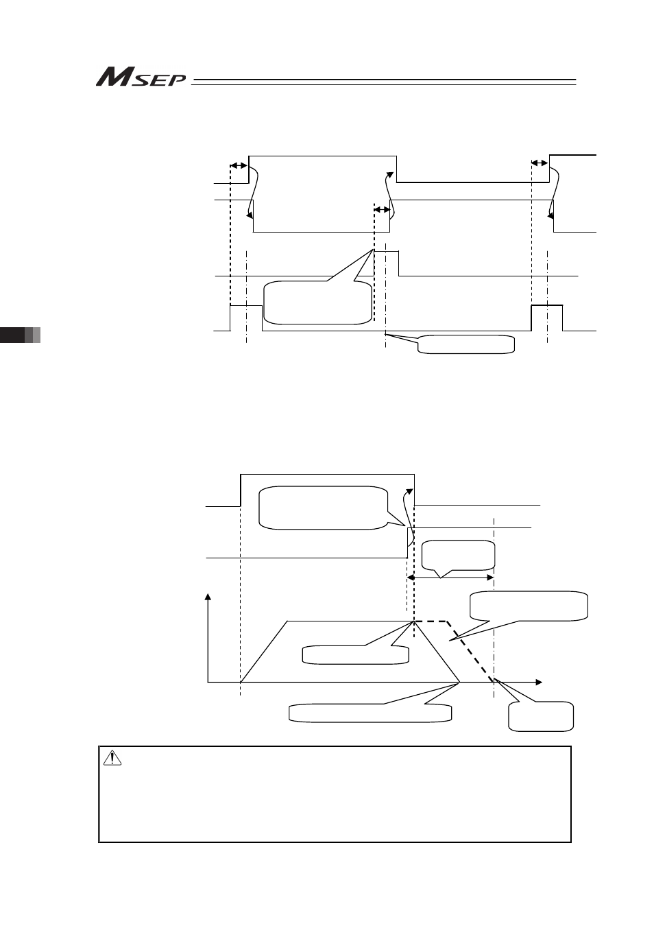
3.8 I/O Signal Controls and Function
166
(Example) Repetition of ST1 ĺ ST2 ĺ ST1 ĺ …
Insert timer ǻt if necessary.
ǻt: Time required to certainly reach the target position after the position sensing output LS1 or 2 is turned ON.
[Example of stop position when the ST* signal is turned OFF by the LS* signal]
If the positioning width is set at a position before the original deceleration start position, the
actuator cannot reach the target position.
Caution: (1) If the ST* signal for the position is turned ON after the completion of
positioning, the LS* signal remains ON.
(2) Both the LS* and PEND signals are set to ON in the positioning width zone.
Accordingly, they may be turned ON under operation of the actuator if a large
positioning width is set.
(3) LS* signal would not be output if the positioning width is set less than the
minimum resolution.
Start signal
ST1
(PLC ĺ Controller)
Turned ON after
entering into
positioning width zone.
Target position
Position sensing output
LS1
(Controller ĺ PLC)
Start signal
ST2
(PLC ĺ Controller)
Position sensing output
LS2
(Controller ĺ PLC)
ǻt
ǻt
ǻt
Start signal
ST1
(PLC ĺ Controller)
Turned ON after
entering into
positioning width zone.
Target
position
Position sensing output
LS1
(Controller ĺ PLC)
Operation of actuator
Stop before target position
Orignal deceleration
start position
Positioning
width
Deceleration start
Speed
Move
distance