IAI America MSEP User Manual
Page 72
Chapter 2 Wiring
64
2.4.9
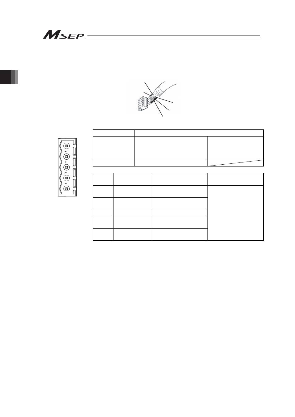
Wiring Layout of Fieldbus Connector
Check the instruction manuals for each Fieldbus master unit and mounted PLC for the details.
1) DeviceNet Type
Shield
BL (CAN L)
RD (V+)
WT (CAN H)
BK (V-)
Connector Name DeviceNet Connector
Cable Side
MSTB2.5/5-ST-5.08 ABGY AU Enclosed in standard
package
Manufactured by
PHOENIX CONTACT
Controller Side
MSTBA2.5/5-G-5.08 ABGY AU
Pin No. Signal Name
(Color)
Description
Applicable cable
diameter
1
2
3
4
5
1
V- (BK)
Power Supply Cable
Negative Side
Front view of connector
on controller side
2
CAN L (BL)
Communication Data
Low Side
3
Shield (None) Shield
4
CAN H (WT)
Communication Data
High Side
5
V+ (RD)
Power Supply Cable
Positive Side
Dedicated cable for
DeviceNet
Note Connect a terminal resistor (121:) between CAN L and CAN H if
the unit comes to the end of the network. [Refer to 2.3 [8] Wiring
Layout for Fieldbus.]
- ERC2 (138 pages)
- ERC2 (188 pages)
- ERC3 (438 pages)
- ERC (153 pages)
- RCA-E (53 pages)
- RCA-P (42 pages)
- RCB-101-MW (38 pages)
- RCP2-C (178 pages)
- RCS-E (102 pages)
- RCA-A4R (72 pages)
- RCA-RA3C (114 pages)
- RCA-SRA4R (56 pages)
- RCA2-RA2AC (100 pages)
- RCA2-SA2AC (92 pages)
- RCA2-TA4C (134 pages)
- RCD-RA1D (40 pages)
- RCP2-BA6 (72 pages)
- RCP2-GRSS (130 pages)
- RCP2-HS8C (126 pages)
- RCP2-RA2C (120 pages)
- RCP2-RTBS (80 pages)
- RCP2W-SA16C (46 pages)
- RCP3-RA2AC (60 pages)
- RCP4-RA5C (82 pages)
- RCP4-SA5C (94 pages)
- RCP4W (96 pages)
- RCS2-F5D (142 pages)
- RCS2-GR8 (46 pages)
- RCS2-RN5N (80 pages)
- RCS2-RT6 (60 pages)
- RCS2-SA4C (258 pages)
- RCS2-TCA5N (62 pages)
- RCL-SA1L (66 pages)
- RCL-RA1L (56 pages)
- RCLE-GR5L (46 pages)
- IK Series (16 pages)
- FS (84 pages)
- IF (76 pages)
- ISB (114 pages)
- ISDA (126 pages)
- ISDB (116 pages)
- ISPWA (90 pages)
- NS (78 pages)
- ICS(P)A (16 pages)
- RS (46 pages)