IAI America MSEP User Manual
Page 73
Chapter 2 Wiring
65
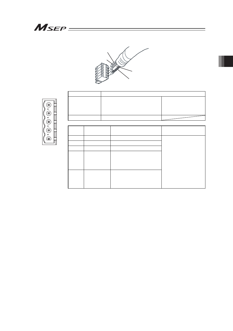
2) CC-Link Type
WT (DB)
BL (DA)
Shield (SLD)
YW (DG)
Connector Name CC-Link Connector
Cable Side
MSTB2.5/5-ST-5.08 ABGY AU
Enclosed in standard
package
Manufactured by
PHOENIX CONTACT
Controller Side
MSTBA2.5/5-G-5.08AU
Pin No. Signal Name
(Color)
Description
Applicable cable
diameter
1
DA (BL)
Communication Line A
1
2
3
4
5
2
DB (WT)
Communication Line B
3
DG (YW)
Digital GND
4
SLD
Connect the shield of the
shielded cable (Connect the
FG of the 5 pins and
controller FG internally)
Front view of
connector on
controller side
5
FG
Frame Ground
(Connect the SLD of the 4
pins and controller FG
internally)
Dedicated cable for
CC-Link
Note Connect a terminal resistor between DA and DB if the unit comes to the
end of the network. [Refer to 2.3 [8] Wiring Layout for Fieldbus.]
- ERC2 (138 pages)
- ERC2 (188 pages)
- ERC3 (438 pages)
- ERC (153 pages)
- RCA-E (53 pages)
- RCA-P (42 pages)
- RCB-101-MW (38 pages)
- RCP2-C (178 pages)
- RCS-E (102 pages)
- RCA-A4R (72 pages)
- RCA-RA3C (114 pages)
- RCA-SRA4R (56 pages)
- RCA2-RA2AC (100 pages)
- RCA2-SA2AC (92 pages)
- RCA2-TA4C (134 pages)
- RCD-RA1D (40 pages)
- RCP2-BA6 (72 pages)
- RCP2-GRSS (130 pages)
- RCP2-HS8C (126 pages)
- RCP2-RA2C (120 pages)
- RCP2-RTBS (80 pages)
- RCP2W-SA16C (46 pages)
- RCP3-RA2AC (60 pages)
- RCP4-RA5C (82 pages)
- RCP4-SA5C (94 pages)
- RCP4W (96 pages)
- RCS2-F5D (142 pages)
- RCS2-GR8 (46 pages)
- RCS2-RN5N (80 pages)
- RCS2-RT6 (60 pages)
- RCS2-SA4C (258 pages)
- RCS2-TCA5N (62 pages)
- RCL-SA1L (66 pages)
- RCL-RA1L (56 pages)
- RCLE-GR5L (46 pages)
- IK Series (16 pages)
- FS (84 pages)
- IF (76 pages)
- ISB (114 pages)
- ISDA (126 pages)
- ISDB (116 pages)
- ISPWA (90 pages)
- NS (78 pages)
- ICS(P)A (16 pages)
- RS (46 pages)