Figure 1-9, And smaller i/o modules installed fr, Figure 1-10 – Grass Valley 4300 Krystal Reference Manual v.3.1 User Manual
Page 23: Some of the fr
Krystal 4300 Reference
1-11
Physical Description
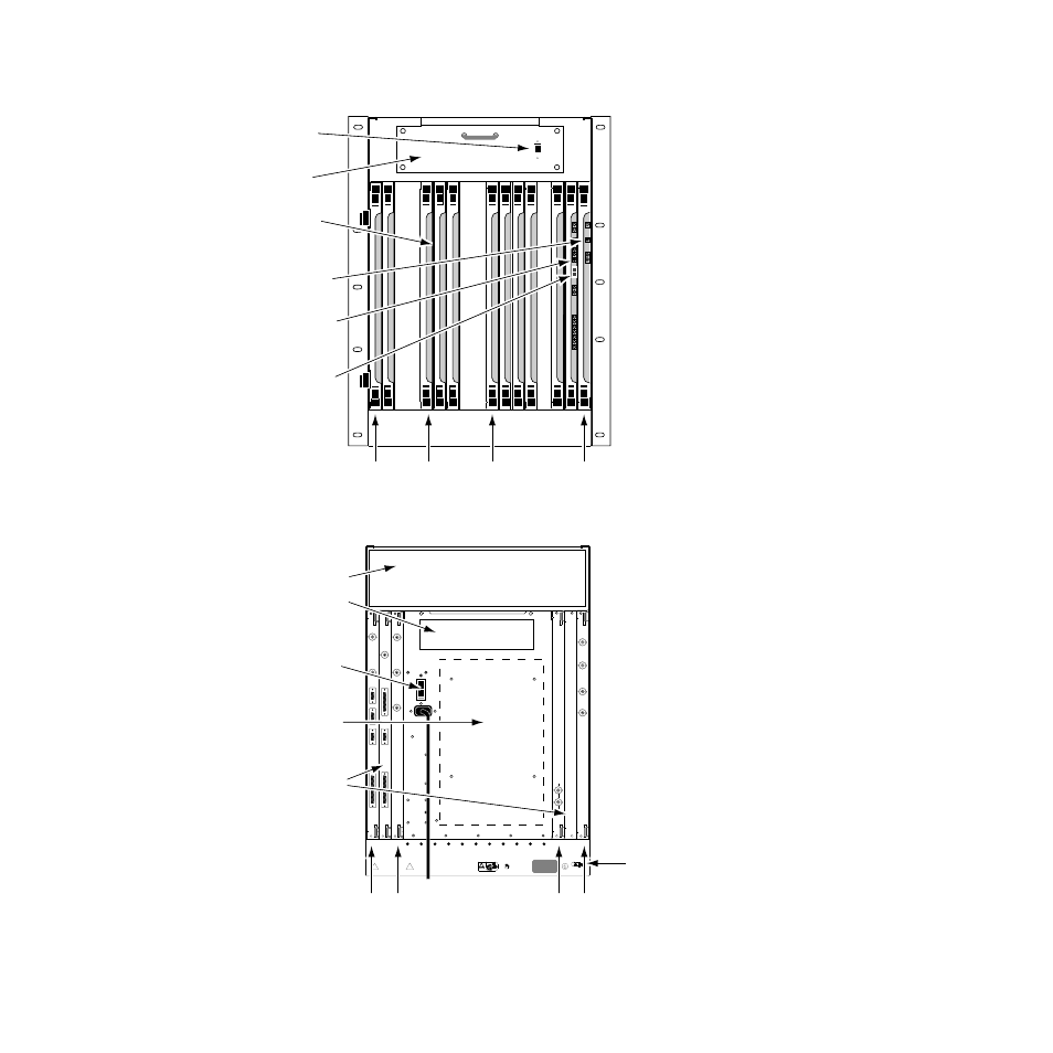
Figure 1-9. Video Processor Frame, Front View
Figure 1-10. Video Processor Frame, Rear View
EFFECTS
MANAGER
I/O
Reset
Sw
Reset
Diag
POWER
DC
+12
+5
–12
Over
Temp
Reset
Diag
TX1
RX1
TX2
RX2
TX3
RX3
FRX
Vid
Reset
Reset
Sw
Vid
Proc
ID
3
4
0600-04
Cooling
Fan
Frame Modules
(Slots 1-17)
DC Power
Switch
Front Door
Removed
Slot 1 Slot 5 Slot 10 Slot 17
Video Processor
CPU Reset Button
Effect Manager
CPU Reset Button
Hardware ID
Slot ... Module
1 ........ Source Effects
2 ........ Input Recursive
3,4 ..... vacant
5 ........ Defocus
6 ........ Filter
- Filter Memory
- Motion Detector
7 ........ Filter Control
8,9 ..... vacant
10 ...... Interpolator (Y-C)
- Memory (2, older systems)
11 ...... Interpolator (Key/Drop Shadow)
- Memory (older systems)
- Memory Option (older systems)
12 ...... Post Transform
- Light Source Option
13 ...... Reverse Address Generator (RAG)
- Kurl (2D Warp) Option
14 ...... vacant
15 ...... Output Recursive
16 ...... Video Processor CPU
17 ...... Effect Manager CPU*
- Graphics
* In multi-channel systems the Effect
Manager CPU (slot 17) is located in the
System Controller frame.
INCLUDING INTERFERENCE THAT MAY CAUSE UNDESIRED OPERATIONS.
THIS DEVICE COMPLIES WITH PART 15 OF THE FCC RULES.
OPERATION IS SUBJECT TO THE FOLLOWING TWO CONDITIONS:
(1) THIS DEVICE MAY NOT CAUSE HARMFUL INTERFERENCE
(2) THIS DEVICE MUST ACCEPT ANY INTERFERENCE RECEIVED
PROFESSIONAL USE
VIDEO EQUIPMENT
LISTED
TUV Rheinland
geprufte
Sicherheit
5J50
RATED VOLTAGE RANGE:90-264 VAC
FREQUENCY: 47-63 Hz
RATED CURRENT: 15 amps
PROGRAM
PREVIEW
KEY/
DEPTH
CONTROL
PANELS
J3
J2
SERIAL
OUTPUT
J1
INPUT A
INPUT B/
MASK
INPUT A
INPUT B
J3
J2
SERIAL
INPUT
J1
J4
KEY
INPUTS
VIDEO
INPUTS
ROUTER
DIAG
J3
J2
J1
VIDEO
PROCESSOR
J4
TALLY
SERIAL
PORTS
GPI
J5
J4
INPUT
J3
OUTPUT
J2
J1
GRAPHICS
EFFECTS
MANAGER
J6
ANALOG
REFERENCE
INPUT
J2
REFERENCE
GENERATOR
J1
l
0
Cooling Exaust
(intakes at bottom
of both sides)
Power Supply
(inside)
I/O Modules
Earth Ground
Lug
AC Power
Switch/Breaker
and AC Line Cord
Slot 17 Slot 15 Slot 3 Slot 1
0600-05
Slot ... Module
1......... Serial Inputs
2......... vacant
3......... Reference Generator
4-14 ... N/A
15....... Serial Outputs
16....... Video Processor I/O*
17....... Effect Manager I/O*
* In multi-channel systems the Effect
Manager I/O is located in the System
Controller Frame and a different Pooled
Video Processor I/O Module is used.