Primary sensor settings, Table 2-14: primary sensor settings, Primary sensor settings -31 – TeeJet Legacy 6000 CAN Guide User Manual
Page 59: Sensor settings definition
Fieldware for the Legacy 6000
Software Version 2.11
Chapter 2 - Getting Started
2-29
Product Control Module (PCM) Setup
Primary Sensor Settings
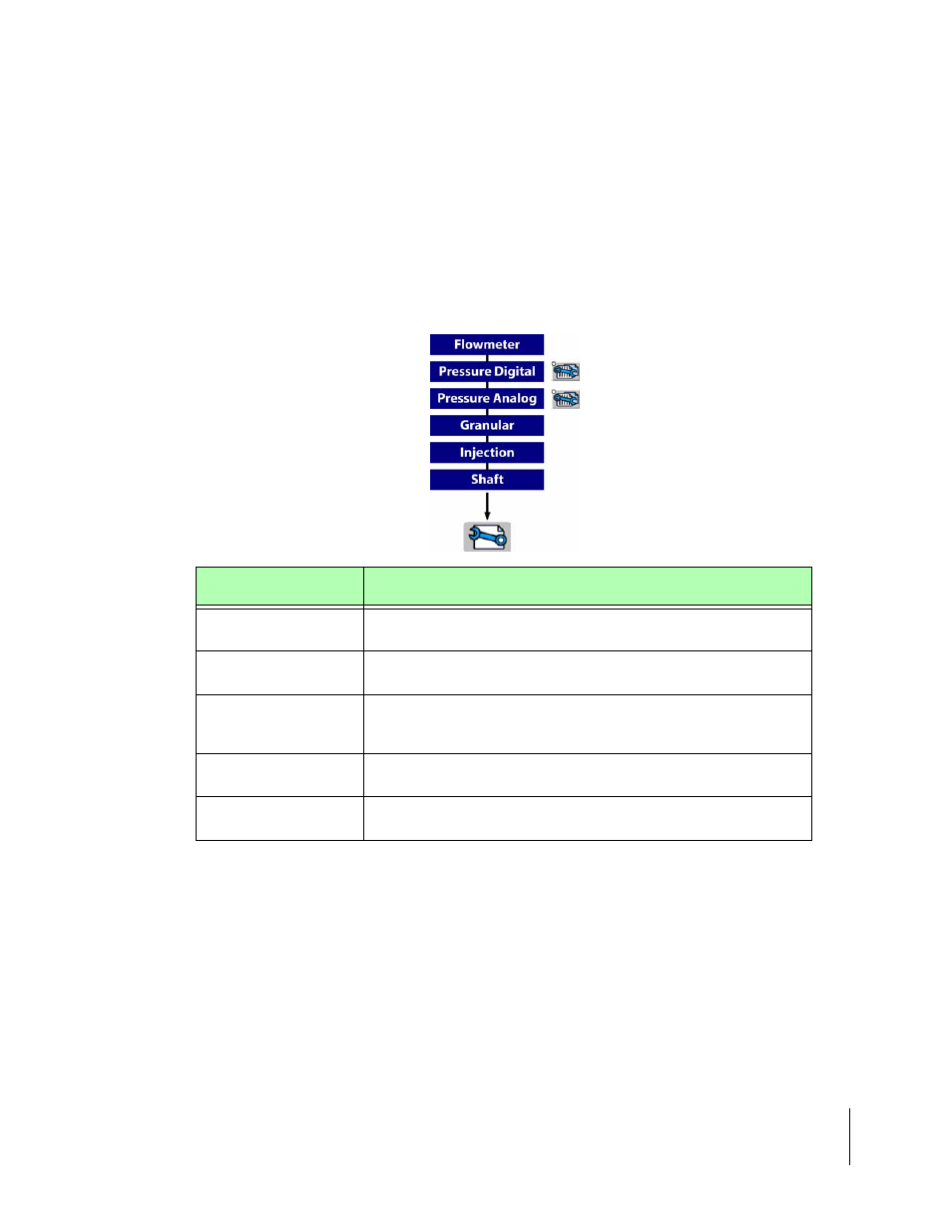
Primary Sensors Flowmeter, Granular, Injection and Shaft have detailed settings that are the
same. Review (Table 2-7) for a detailed description of the settings. The two other Primary Sensors,
Pressure Digital and Pressure Analog, have the initial settings as well as an sub settings. To
access the sub settings locate the two Settings Buttons on the right side of the screen, use the two
buttons to swap between settings.(Figure 2-32). Review (Table 2-14) for a detailed Description of
the initial settings and (Table 2-15) for a detailed description of the sub settings for Pressure Digital
and Pressure Analog senors.When the Primary Sensor settings and parameters are selected,
press the Forward arrow to advance to the next PCM Setup page
Sensor Settings
Definition
Input
Defines digital and analog sensors. Senor inputs A-D are digital (flowemeter,
and slot sensors) and Senors E-F are analog (pressure).
Sensor Name
A user defined name used to label a particular sensor or monitor. This informa-
tion is not stored in the PCM and is used for messaging to the user only.
Calibration Number
Enter calibration number in units specified, this number is normally found on
the sensor. Physical calibration will further fine-tune this number. For NH3
applications (See “Appendix C - NH3 Application” on page C-1.)
Cal# Basis
Table of preset calibration numbers. This can be used to rapidly change a cali-
bration number. See Appendix B for Cal# Basis setup.
Nozzle Constant
Only use for Pressure application. Enter the gal/min rating of your nozzle at
10mph at 30psi
Table 2-14: Primary Sensor Settings