Arm setup detailed description, Table 3-4: arm setup item description, Arm setup detailed description -32 – TeeJet Legacy 6000 CAN Guide User Manual
Page 102: Table 3-4 list
3-32
Chapter 3 - Real-time Setup
ARM Setup
Fieldware for the Legacy 6000
Software Version 2.11
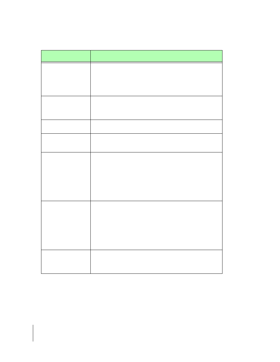
ARM Setup Detailed Description
Setup Item
Description
Record File (.RCD)
The spray trajectory data for a particular PCM/product application is
stored in the Record file. The Record file contains rate, spray on and
spray off data, and report data entered in the Job Report, as well as
total boom width information. This file can be imported into the Field-
ware Map Manager program where an application report can be gen-
erated. Maps of a (.RCD) file are known as “as applied” maps.
Guideline File (.GLN)
The Guideline file contains all information required to reconstruct the
guidelines created and used during product application. This file can
contain multiple guidelines in any orientation and can contain guide-
lines for any application task.
Map File (.GMF)
A Map file is used to store additional field features which might be
necessary to locate during product application.
Boundary File (.BND)
The Boundary file can be used to show an existing field boundary or
create a new field boundary. Mapping the filed boundary provides
valuable area information.
Auto Hold
Auto Hold has three options: Boom Center of Full Swath, Boom End
of Full Swath, and Section Center of each section (see "Auto
Boom Shutoff (Section Center)" on page 2-33). Each allows the
controller to automatically turn spray activity off when the vehicle
drives over a previously applied area. Center of Full Boom requires
that the center of the boom be in an already applied area. Ends of Full
Boom requires that the left end, right end and center of the boom be
in an already applied area. Both options use the System Delay to
compute the position of the boom.
System Delay
The System Delay is the number of seconds that the ARM program
looks out in front of the vehicle. Based on the vehicles trajectory and
this system delay value, the Application Rate Management program
can determine where the vehicle is with respect to the prescription
map. By looking out in front of the vehicle, the ARM program can
identify the required rate for an upcoming prescription map region and
notify the rate controller of any changes. This can help minimize lag
times in the product delivery system when changing product rates. A
value of two seconds is recommended.
GSO Speed
The Ground Speed Override (GSO) Speed is a desired minimum
speed. When the vehicle speed drops below the GSO Speed, the
GSO Speed is used. When the vehicle speed increases above the
GSO Speed, then the vehicle speed is used.
Table 3-4: ARM Setup Item Description