Appendix b - creating a calibration table, Creating a calibration table on a pc – TeeJet Legacy 6000 CAN Guide User Manual
Page 189
Fieldware for The Legacy 6000
Software Version 2.11
B-1
Appendix B - Creating a Calibration Table
Appendix B - Creating a Calibration Table
A Calibration Table can be created two way, Midwest Technologies recommends the table be cre-
ated on a PC and loaded on the Legacy. The second option is to create the table Using the Legacy
6000. A Calibration Table allows the operator to select from a predefined set of calibration #’s that
are commonly used. An example would be a granular application in which the gate height changes
frequently resulting in the change of the calibration #. The instructions below will use a gate height
Calibration Table as an example.
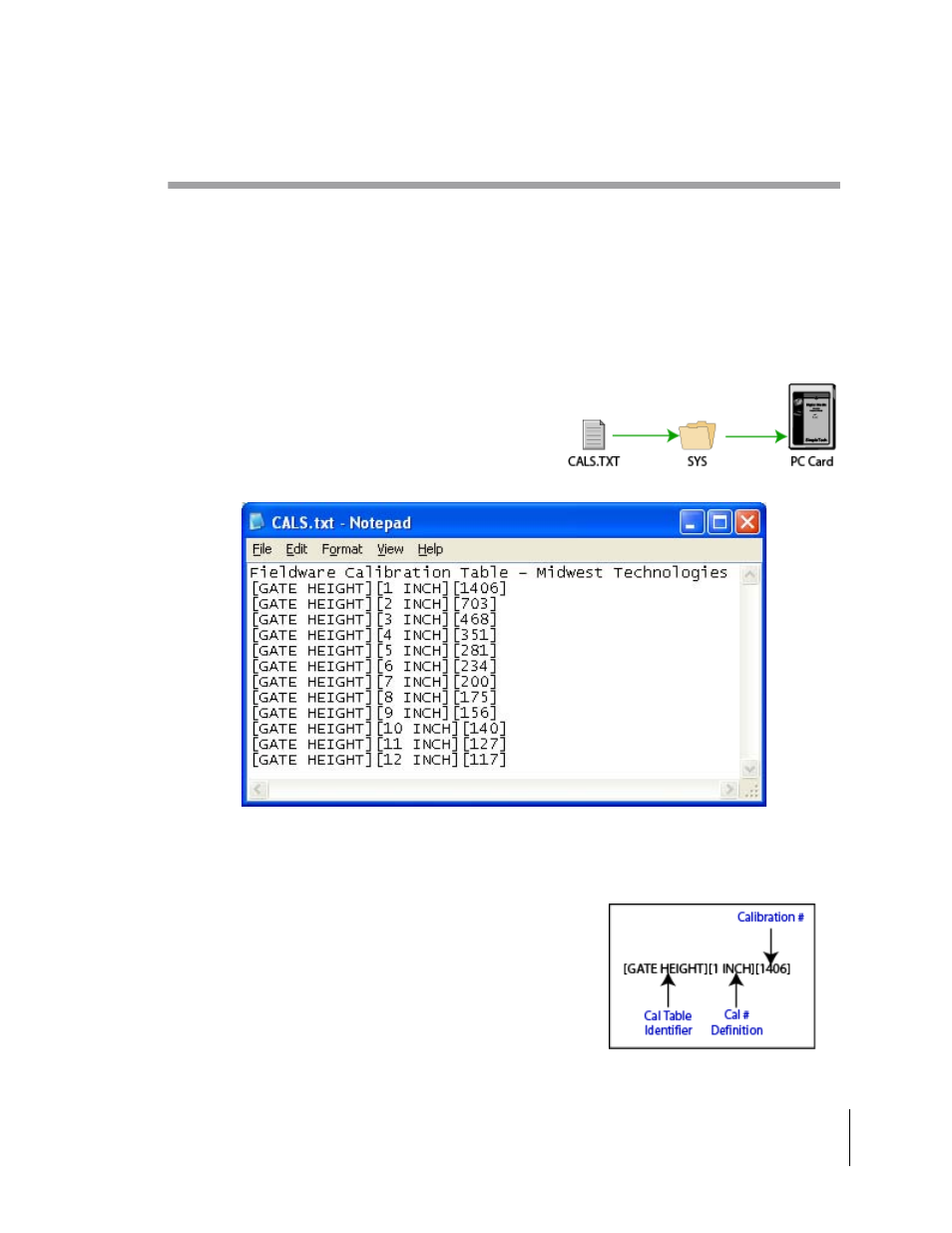
Creating a Calibration Table on a PC
Create a calibration table with a text editor such as
NOTEPAD and save the file as “CALS.TXT” in folder
labeled “SYS” on PC Card for the Legacy 6000.
Here shown is a calibration table providing nominal calibration numbers for a granular system that
employs Gate Height ranging from 1 to 12 inches. A valid entry must have three fields separated
by square brackets within the bracket there must be some text [GATE HEIGHT][1 INCH][1406].
The Calibration Identifier will be the table name or label when
loading the table in the Legacy 6000. Cal # Definition defines
the calibration # related to it. The calibration number must be
greater than zero and the units must relate to those selected in
PCM Sensor Setup on the Legacy 6000. For example; if the
sensor units are lbs/ac the Cal Table calibration #’s must be
pul/lb.