The headland guidance pattern, Applying multiple headland circuits, Figure 4-17: operating in headland pattern – TeeJet Legacy 6000 CAN Guide User Manual
Page 129: The headland guidance pattern -15, Applying multiple headland circuits -15
Fieldware for the Legacy 6000
Software Version 2.11
Chapter 4 - Real-time Operation
4-15
Real-time Guidance Operation
The Headland Guidance Pattern
This section describes how to operate the Headland guidance pattern. The Headland pattern is
selected when the operator wants to drive several circuits around the field boundary and be guided
around all circuits that occur after the first circuit. When several headland circuits have been com-
pleted, the operator then has the choice of switching back to the Straight-Line pattern. The Head-
land pattern is also selected when a user wants to do product application on terraced fields. In the
Headland curved guidance pattern, the operator can pull along side any previous applied swath
and be guided parallel to that swath.
Applying Multiple Headland Circuits
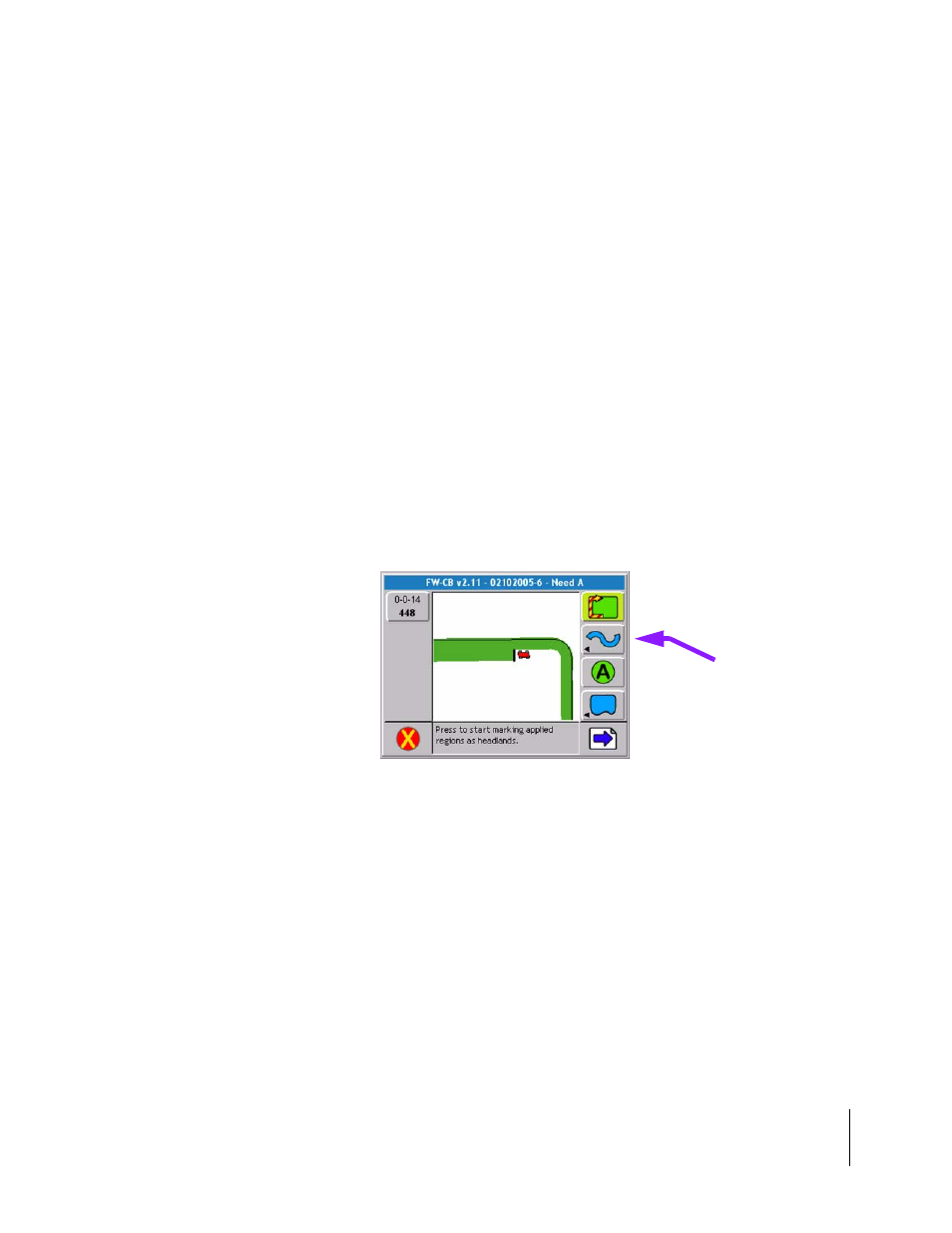
Figure 4-17 shows the Map page when the Headland pattern is selected. While operating in the
Headland pattern, the user has the option to mark the A and B points for the Straight-Line pattern.
This feature makes it easier for the operator to Mark the A and B points while in curved mode
applying the headlands. It is always best to mark the A and B points for the Straight-Line pattern
while driving along a straight edge of a field.
The operator will remain in the Headland pattern until the pattern is changed using the Guidance
Pattern soft-key, see (Changing Guidance Pattern on page 5-13). The A and B points are only
required for the Straight-Line pattern. The Headland pattern does not require an A-B line.
Figure 4-17: Operating in Headland Pattern
Guidance Pattern
Soft-key