1 combination of master axes and slave axes, Chapter 2 operations 61 – IAI America XSEL-S User Manual
Page 69
Chapter 2 Operations
61
Master axis
RC controller
Slave axis
Extension motion control board 1
Extension motion control board 2
Slave axis
Main CPU control axis
Main CPU control axis
Extension motion control board control axis
Extension motion control board control axis
RC controller
Slave axis
Extension motion control board 1
Slave axis
Master axis
Master axis
Master axis
Synchronization control can be performed for up
to 17 axes (1 master axis and 16 slave axes).
Synchronization is
possible only for axes
connected to the same
extension motion control
board.
Synchronization among
multiple boards is not
possible
Synchronization control can be performed for up
to 8 axes (1 master axis and 7 slave axes).
Up to 8 axes
can be
connected
Up to 8 axes
can be
connected
Up to 6 axes
can be
connected
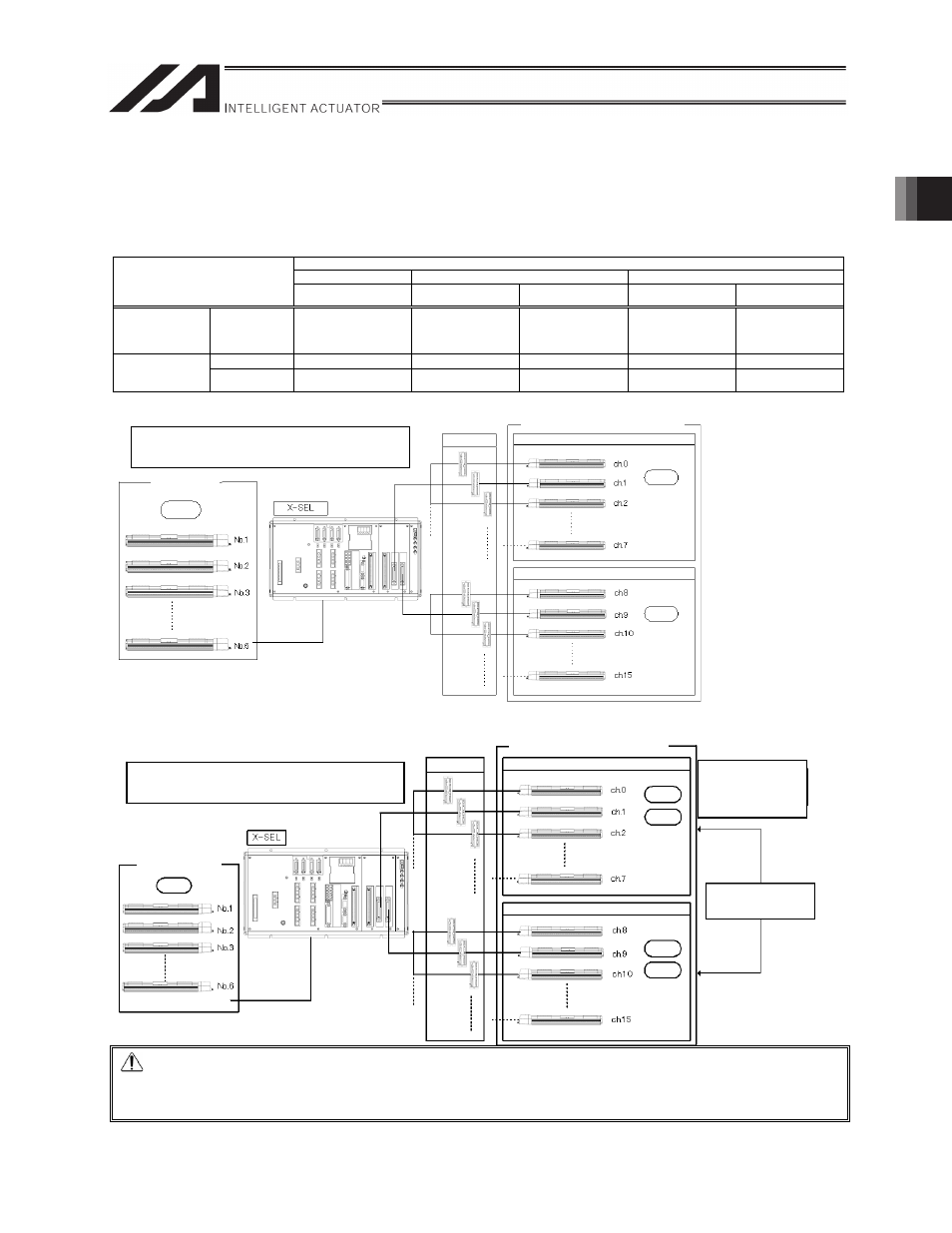
2.4.1 Combination of Master Axes and Slave Axes
This section explains combination of slave axes allowed for the main axis setting.
The table below shows combination of slave axes that can be controlled in a given setting.
* Assignment of main and slave axes is specified in programs (XCAS commands).
{
: Allowed X: Not allowed
Main axis
Main CPU control axis Extension motion control board control axis Extension motion control board input channel
Slave axis
XSEL-P/Q Axis No. 1 to 6
XSEL-R/S Axis No. 1 to 8
Axis No. 0 to 7
Axis No. 8 to 15
CH No. 0 to 1
CH No. 2 to 3
Main CPU control
axis
XSEL-P/Q Axis
No. 1 to 6
XSEL-R/S Axis
No. 1 to 8
{
{
{
{
{
Axis No. 0 to 7
{
{
x
{
x
Extension motion
control board
control axis
Axis No. 8 to 15
{
x
{
x
{
[1] When main axis is main CPU control axis
[2] When main axis is extension motion control board control axis
Caution
If two extension motion control boards are installed, synchronized operation among the two boards is not
possible.
Extension motion control board 2