㪧㪚㪦㪥䋭㪧㪣, 㪯㪪㪜㪣㪄㪧㪆㪨, Pcon䋭pl – IAI America XSEL-S User Manual
Page 33: Xsel-p/q, Acon – pl
Chapter 1 Installation and W
iring
25
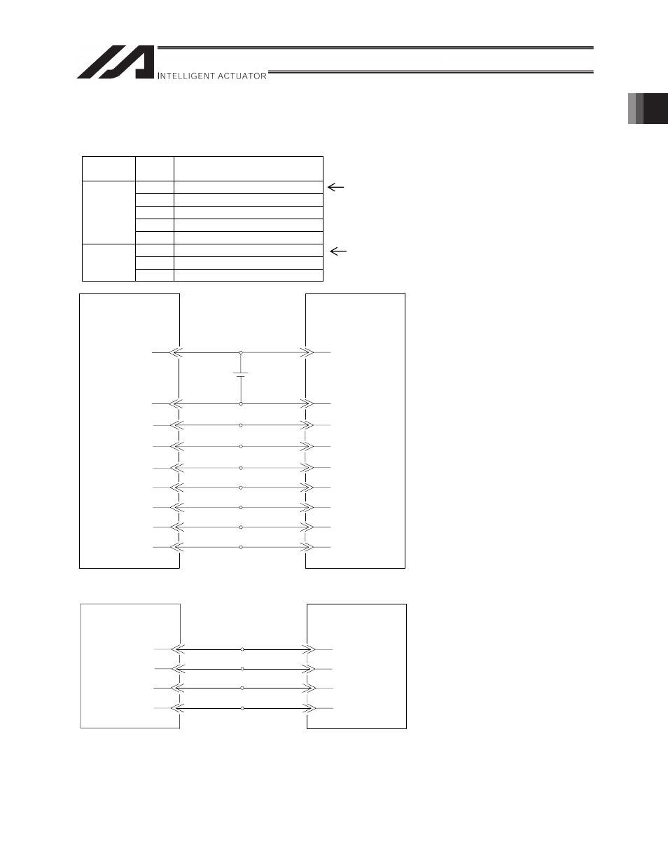
Connection Diagram (XSEL-P/Q PCON-PL/ACON-PL)
I/O section
Perform the wiring in the following continuous order.
Pulse I/O section
Assign the head input No. using I/O parameters (see section 2.3.1).
Assign the head output No. using I/O parameters (see section 2.3.1)
Direction
Wiring
order
Signal name
1
SV (Servo ON status)
2
INP (Position complete status)
3
HEND (Home return completion status)
4
ALM (Alarm status)
Input
(X-SEL
side)
5
RMDS (Operation mode status)
1
SON (Servo ON command)
2
HOME (Home return command)
Output
(X-SEL
side)
3
RES (Alarm reset)
㪈
Black
㪛㪚䋲䋴䌖
㪊
White/black
㪉
Red
㪍
㪌
㪛㪚㪇䌖
㪇㪇㪈
㪟㪦㪤㪜
Green
㪪㪭
White/green
㪎
Yellow
䌒䌅䌓
㪘㪣㪤
㪏
White/yellow
㪠㪥㪧
㪐
Brown
㪈㪇
㪟㪜㪥㪛
㪧㪚㪦㪥䋭㪧㪣
24-V power supply for
I/O signals
㪈
Brown
1
㪌㪇
Black 5
㪯㪪㪜㪣㪄㪧㪆㪨
㪛㪚䋲䋴䌖
㪛㪚㪇䌖
㪊
㪋
White/brown
㪊㪎
㪌
㪊㪏
㪊㪐
㪇㪇㪉
㪇㪇㪊
㪊㪇㪊
㪊㪇㪋
㪊㪇㪌
Orange 1
Yellow 1
Green 1
㪮㪿㫀㫋㪼㪋
㪙㫃㪸㪺㫂㪋
Purple 4
Gray
㪋
㪪㪦㪥
(The I/O port numbers are for
reference only.)
㪇㪇㪋
㪍
PCON䋭PL
Blue
㪙㫉㫆㫎㫅
㪞㫉㪼㪼㫅
Orange
㪈㪈
Blue
㪈㪉
White/blue
㪈㪊
Gray
㪈㪋
White/gray
㪆㪧㪧
㪧㪧
㪆㪥㪧
㪥㪧
Pulse output phase
A, + side
XSEL-P/Q
㪈
㪉
㪊
㪋
Pulse output phase
A, - side
Pulse output phase
A, - side
Pulse output phase
B, - side
(When connecting to channel
No. 0)
Pin No.
Pin No.
Pin No.
Pin No.
Board name
Signal name
Signal name
ACON – PL