IAI America XSEL-S User Manual
Page 130
Chapter 3 Programs
122
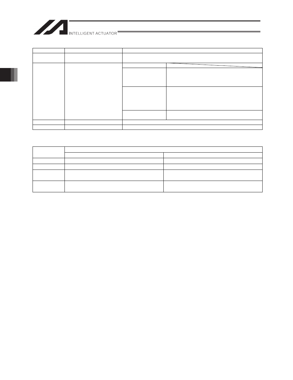
Variable No.
Data name
Description
n + 6
Slave axis stroke length
storage position No.
* Specify position No. of extension motion control board control slave axis (0
to maximum position No.)
Master axis type
0
Master axis synchronization start position storage
position No.
(Note) Specify position No. of main CPU control
master axis (0 to maximum position No.)
1
Master axis synchronization start position storage
position No.
(Note) Specify position No. of extension motion
control board control master axis (0 to
maximum position No.)
n + 7
Master axis synchronization
start position (storage position
No.)
* Valid only when “master axis
arriving specified
synchronization position” is
selected as synchronization
type
2
Master axis synchronization start position (pulse
unit)
n + 8
Reserved
Make sure to set 0.
n + 9
Reserved
Make sure to set 0.
Synchronization type (variable No. n)
Description
Setting value
Synchronization start type
Synchronous movement repeat type
0
Immediate
One cycle only
1
Immediate
Repeat
2
Master axis arriving specified
synchronization position
One cycle only
3
Master axis arriving specified
synchronization position
Repeat
Synchronous movement continues until:
[1] The XSYE command is executed (synchronous movement is stopped).
[2] The operation of slave axes is stopped (XSTP/CANC commands).
[3] The synchronous movement repetition type is single cycle only and the master axis reached the
stroke end.
[4] The slave axis movement program that executed the XCAS command is terminated.
x
The master axis stroke length/stroke end position and master axis synchronization start position shall
be set to position data of the master axis if the master axis is a main CPU control axis or extension
motion control board control axis. If the master axis is a pulse input channel, set them directly to
variables for movement settings. The slave axis stroke length is set in slave axis position data.
x
If master axis stroke end position is specified for the stroke type, the master axis stroke length (single
cycle) of electronic CAM tables becomes [master axis stroke end position – synchronization start
master axis position]. The relationship of the master axis position with electronic CAM table phases is
as follows: phase 0 corresponds to synchronization start master axis position, and the positive phase
direction is the direction to move from synchronization start master axis position toward master axis
stroke end position.
x
If master axis stroke length is specified for the stroke type, the relationship of the master axis position
with electronic CAM table phases is as follows: phase 0 corresponds to synchronization start master
axis position, and the positive phase direction corresponds to master axis coordinate positive move
direction when the stroke length has a positive coordinate value and the minus phase direction
corresponds to master axis coordinate positive move direction when the stroke length has a negative
coordinate value.