IAI America XSEL-S User Manual
Page 32
Chapter 1 Installation and W
iring
24
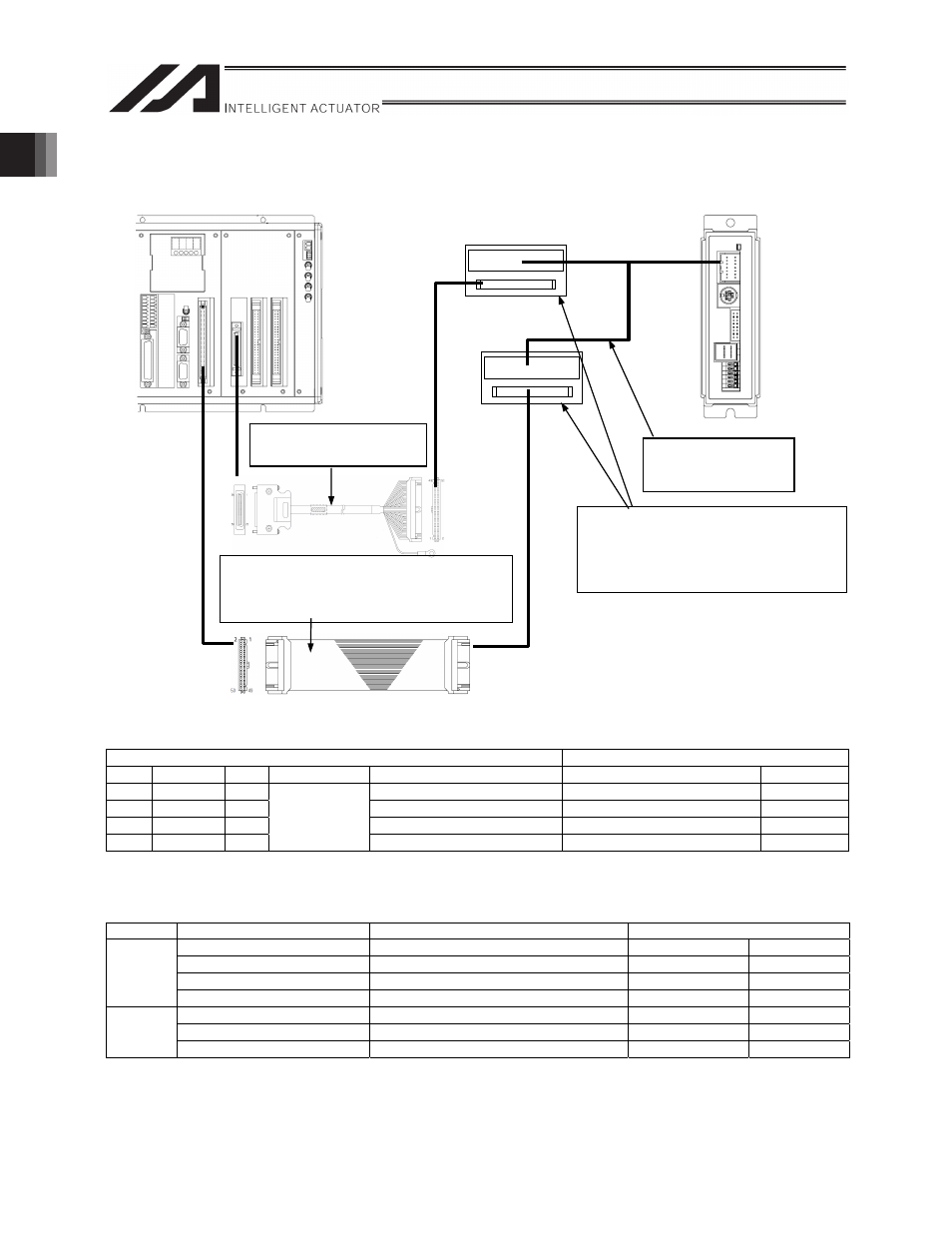
1.6.2 Connecting XSEL-PQ to PCON-PL/ACON-PL
X-SEL-P/Q
x
The following pulse train inputs are connected for each axis.
Example: Connecting to channel 0
X-SEL-P/Q side
PCON-PL/ACON-PL side
No. Line color I/O
Channel No.
Function
Function
Line color
1
Blue
Out
Pulse output phase A, + side
PP (PIO connector 12)
White/blue
2
Orange
Out
Pulse output phase A, - side
/PP (PIO connector 11)
Blue
3
Green
Out
Pulse output phase B, + side
NP (PIO connector 14)
White/gray
4
Brown
Out
0
Pulse output phase B, - side
/NP (PIO connector 13)
Gray
* Refer to section 1.7.1 “Pulse Train Cables” for assignment of other channels.
x
The following I/Os are connected for each axis.
* I/O assignment on the X-SEL-P/Q side is performed using parameters (see section 2.3.1).
Direction
X-SEL-P/Q side
Function
PCON-PL/ACON-PL side
General-purpose input
SV (Servo ON status)
PIO connector 7
Yellow
General-purpose input
INP (Position complete status)
PIO connector 8
White/yellow
General-purpose input
HEND (Home return completion status) PIO connector 9
Brown
Input
General-purpose input
ALM (Alarm status)
PIO connector 10 White/brown
General-purpose output
SON (Servo ON command)
PIO connector 3
Red
General-purpose output
HOME (Home return command)
PIO connector 5
Green
Output
General-purpose output
RES (Alarm reset)
PIO connector 6
White/green
Connector terminal block conversion unit
The customer shall provide the unit.
* The connector can be disconnected and
normal terminal blocks can be used.
(ex. OMRON – Model:XW2D-50G6)
PIO Cable
CB-PAC-PIO
(attached to SCON)
Pulse I/O cable
CB-XPQ-PLIOS -H6
PIO Cable
CB-X-PIO With connector on one side only
CB-X-PIO -H6 With connectors on both sides
CB-X-PIOH With connector on one side only
PCON-PL/ACON-PL