Pcon-ca, X-sel-p/q – IAI America XSEL-S User Manual
Page 35
Chapter 1 Installation and W
iring
27
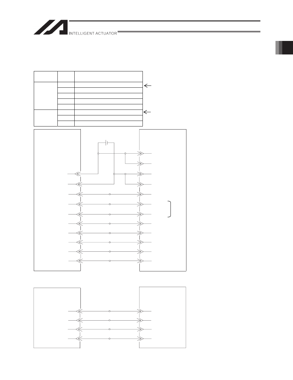
Connection Diagram (XSEL-P/Q PCON-CA)
I/O section
Perform the wiring in the following continuous order.
Direction
Wiring
order
Signal name
1
SV (Servo ON status)
2
INP (Position complete status)
3
HEND (Home return completion status)
4
ALM (Alarm status)
Input
(X-SEL
side)
5
RMDS (Operation mode status)
1
SON (Servo ON command)
2
HOME (Home return command)
Output
(X-SEL
side)
3
RES (Alarm reset)
Assign the head input No. using I/O parameters (see Section 2.3.1).
Assign the head output No. using I/O parameters (see Section 2.3.1).
DC24V
DC0V
001
HOME
SV
RES
ALM
INP
HEND
PCON-CA
24 V power supply
for I/O signals
1
50
X-SEL-P/Q
DC24V
DC0V
3
4
37
5
38
39
002
003
303
304
305
Green1
white4
Black4
SON
004
6
DC24V
DC0V
1A
2A
19B
20B
5A
6A
7A
2B
3B
4B
6B
Black4
005
7
8B
RMDS
Brown1
(For standard I/O)
4A
3A
18B
17B
/PP
PP
/NP
NP
X-SEL-P/Q
1
2
3
4
PCON-CA
*1
(The I/O port number are
forreference only.)
Brown1
Black5
Orange1
Yellow1
Purple4
Gray4
Red1
white4
black4
Green1
Purple1
Blue1
Red3
Orange3
Yellow3
Blue3
Gray3
(When connecting
to channel No.0)
Pulse output phase
A,+ side
Pulse output phase
A,- side
Pulse output phase
B,+ side
Pulse output phase
B,- side
Blue
Orange
Green
Brown
Orange-1
Yellow-1
Purple-4
Gray-4
*1 Note that the wiring order is 7A (HOME) and then 6A (RES).
Pulse I/O section