IAI America XSEL-S User Manual
Page 68
Chapter 2 Operations
60
Phase Disp.
x
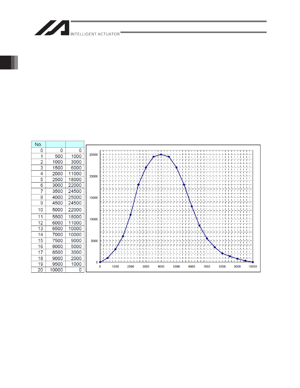
CAM table
CAM table is a collection of point data of which horizontal axis is set as phase of the master axis
and vertical axis is set as displacement of the slave axis (herein after referred to as "displacement
data.")
Phase/displacement is not a physical quantity, but indicates the ratio relative to the maximum
value. The value of the stroke amount of the master/slave axes (width the master/slave axes can
move in 1 cycle of the CAM movement) multiplied by these ratios are movement amount
(movement amount from synchronization start position).
Relative position from master axis synchronization start position = master axis stroke x current phase
/ maximum phase
Relative position from slave axis synchronization start position = slave axis stroke x current
displacement / (maximum displacement – minimum displacement)
[Example] CAM table
Figure 2.4.1 CAM Table Example
Up to 64 CAM tables and up to 16,384 displacement data in total for all tables can be defined. (Refer to
item [1] of “2.3.3 Extension Motion Control Board Parameter Settings (2) Common Parameters” for
details.)
Phase
(Master axis)
Displacement (Slave axis)