4 connecting x-sel r/s to scon-c/scon-ca – IAI America XSEL-S User Manual
Page 36
Chapter 1 Installation and W
iring
28
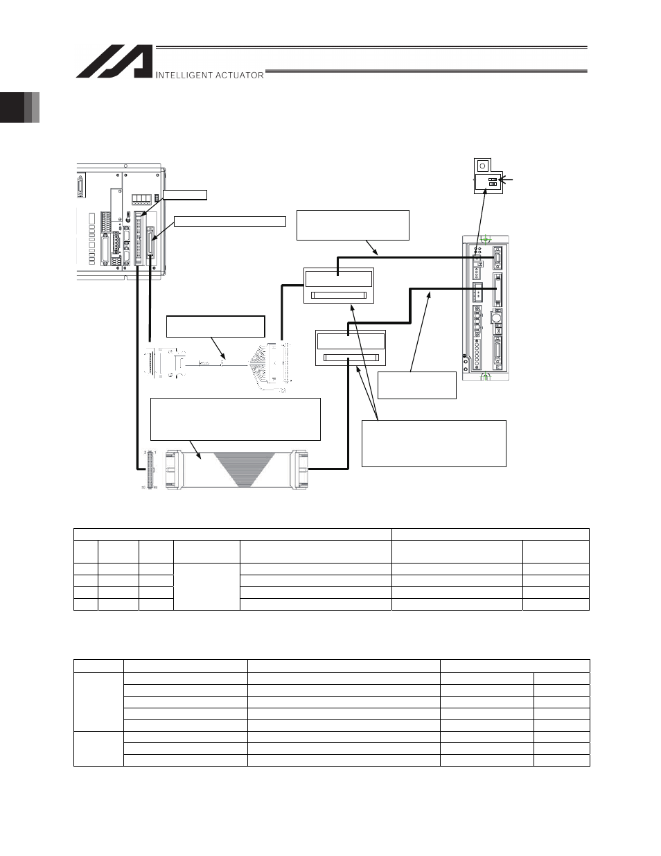
1.6.4 Connecting X-SEL R/S to SCON-C/SCON-CA
(A single extension motion control board is to be used).
XSEL-R/S
1
2
O
N
ADRS
SCON
I/O board
Toggle the piano switch on the controller’s front panel
to the pulse train mode.
Turn the power supply off and turn SW1 ON (turn over to the left).
Pulse train control service cable
CB-SC-PIOS
(Option)
PIO Cable
CB-X-PIO
With connector on one side only
CB-X-PIO
-H6 With connectors on both sides
CB-X-PIOH
With connector on one side only
Pulse I/O cable
CB-XPQ-PLIOS
-H6
PIO Cable
CB-PAC-PIO
(attached to SCON)
Connector terminal block conversion unit
The customer shall provide the unit .
*The connector can be disconnected
and normal terminal blocks can be used.
(ex. OMRON – Model:XW2D-50G6)
Extension Motion Control Board
x
The following pulse train inputs are connected for each axis.
Example: Connecting to channel 0
X-SEL-R/S side
SCON-C/CA side
No.
Line
color
I/O
Channel No.
Signal name
Signal name
Line color
1
Blue
Out
Pulse output phase A, + side
Pulse train connector 3 (PP)
Red
2 Orange Out
Pulse output phase A, - side
Pulse train connector 4 (/PP)
White/red
3
Green
Out
Pulse output phase B, + side
Pulse train connector 5 (NP)
Green
4
Brown
Out
0
Pulse output phase B, - side
Pulse train connector 6 (/NP) White/green
* Refer to section 1.7.1 “Pulse Train Cables” for assignment of other channels.
x
The following I/Os are connected for each axis. Servo ON status (SV)
* I/O assignment on the X-SEL side is performed using parameters (see Section 2.3.2).
Direction
X-SEL-R/S side
Signal name
SCON-C/CA side
General-purpose input
SV (Servo ON status)
PIO connector 2B
Red-3
General-purpose input
INP (Position complete status)
PIO connector 3B
Orange-3
General-purpose input
HEND (Home return completion status)
PIO connector 4B
Yellow-3
General-purpose input
ALM (Alarm status)
PIO connector 6B
Blue-3
Input
General-purpose input
RMDS (Operation mode status)
PIO connector 8B
Gray-3
General-purpose output SON (Servo ON command)
PIO connector 5A
Green-1
General-purpose output HOME (Home return command)
PIO connector 7A
Purple-1
Output
General-purpose output RES (Alarm reset)
PIO connector 6A
Blue-1