Perform wiring in series in the following order, Scon-c/ca, X-sel-p/q – IAI America XSEL-S User Manual
Page 31: S-con-c/ca
Chapter 1 Installation and W
iring
23
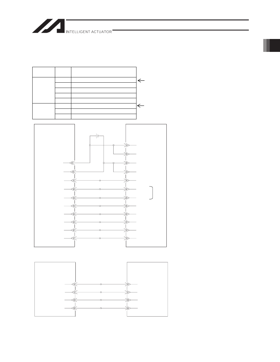
Connection Diagram (X-SEL-P/Q SCON-C/SCON-CA)
I/O section
Perform wiring in series in the following order.
Direction
Wiring
order
Signal name
1
SV (Servo ON status)
2
INP (Position complete status)
3
HEND (Home return completion status)
4
ALM (Alarm status)
Input
(X-SEL
side)
5
RMDS (Operation mode status)
1
SON (Servo ON command)
2
HOME (Home return command)
Output
(X-SEL
side)
3
RES (Alarm reset)
Assign the head input No. using I/O parameters (see Section 2.3.1).
Assign the head output No. using I/O parameters (see Section 2.3.1).
*1 Note that the wiring order is 7A (HOME) and then 6A (RES).
DC24V
DC0V
001
HOME
SV
RES
ALM
INP
HEND
SCON-C/CA
24-V power supply
for I/O signals
1
Brown1
50
Black 5
X-SEL-P/Q
DC24V
DC0V
3
4
37
5
38
39
002
003
303
304
305
Orange1
Yellow1
Green1
Black4
Purple4
Gray4
SON
(The I/O port numbers are for
reference only.)
004
6
DC24V
DC0V
1A
2A
19B
20B
5A
6A
7A
2B
3B
4B
6B
005
7
8B
RMDS
Brown1
Red1
White4
Black 4
Green1
Purple1
Blue1
Red3
Orange3
Yellow3
Blue3
Gray3
(For standard I/O)
White4
Black4
4
White/red
3
Red
6
Green
5
White/green
Blue
Pulse output phase
A, + side
Brown
Green
/PP
PP
/NP
NP
Orange
X-SEL-P/Q
1
2
3
4
S-CON-C/CA
Pulse output phase
A, - side
Pulse output phase
B, + side
Pulse output phase
B, - side
(When connecting
to channel No. 0)
*1
Pin No.
Pin No.
Pin No.
Pin No.
Board name
Signal name