4 sample programs, 1 cases where main axis is main cpu control axis – IAI America XSEL-S User Manual
Page 142
Chapter 3 Programs
134
3.4 Sample Programs
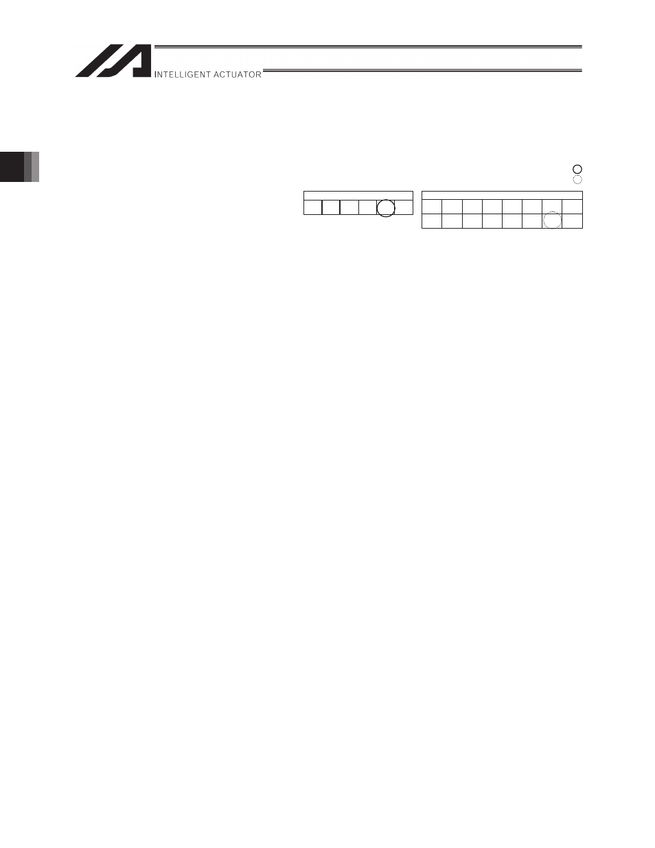
3.4.1 Cases where Main Axis is Main CPU Control Axis
Conditions:
Main axis No. 2
Slave axes No. 0 and 1
Electronic table No. 5
Stroke type: 0
Immediate start (execute 1 cycle)
Program example
LET
200
1
Set “synchronization type = 1 (immediate start/one-cycle only
operation)” to variable No. 200.
LET
201
0
Set “master axis type = 0 (main CPU control axis)” to variable
No. 201.
LET
202
2
Set “master axis No. = 1” to variable No. 202.
LET
203
5
Set “electronic CAM table No. = 0” to variable No. 203.
LET
204
0
Set “stroke type = 1 (master axis stroke length specification)”
to variable No. 204.
LET
205
2
Set “master axis stroke end position storage position No. = 2”
to variable No. 205.
LET
206
0
Set “slave axis stroke length storage position No. = 0” to
variable No. 206.
LET
207
0
Set 0 to variable No. 207 (unused data).
LET
208
0
Set 0 to variable No. 208 (reserved area).
LET
209
0
Set 0 to variable No. 209 (reserved area).
XCAS
0
200
Start synchronous electronic CAM movement of extension
motion control board axis 0 with the synchronous electronic
CAM movement settings specified in variable No. 200 to 209.
XCAS
1
200
Start synchronous electronic CAM movement of extension
motion control board axis 0 with the synchronous electronic
CAM movement settings specified in variable No. 200 to 209.
ACC
0.3
Set the acceleration of the main axis to 0.3G.
DCL
0.3
Set the deceleration of the main axis to 0.3G.
VEL
100
Set the moving speed of the main axis to 100 mm/sec.
MVOP
10
Move the specified axis (main CPU control axis No. 2) to
position No. 10.
XSYE
0
End synchronization of extension motion control board No. 0.
EXIT
End the program.
Extension motion control board
Ch.
No.15
Ch.
No.14
Ch.
No.13
Ch.
No.12
Ch.
No.11
Ch.
No.10
Ch.
No.9
Ch.
No.8
Ch.
No.7
Ch.
No.6
Ch.
No.5
Ch.
No.4
Ch.
No.3
Ch.
No.2
Ch.
No.1
Ch.
No.0
Main CPU control axis
Axis
No. 6
Axis
No. 5
Axis
No. 4
Axis
No. 3
Axis
No. 2
Axis
No. 1
Main axis
Slave axis