System overview, Electronics – Luminex 100 IS Version 2.2 User Manual
Page 34
3 - 8
PN 89-00002-00-069 Rev. A
Luminex 100 IS User Manual Version 2.2
x
MAP Technology
System Overview
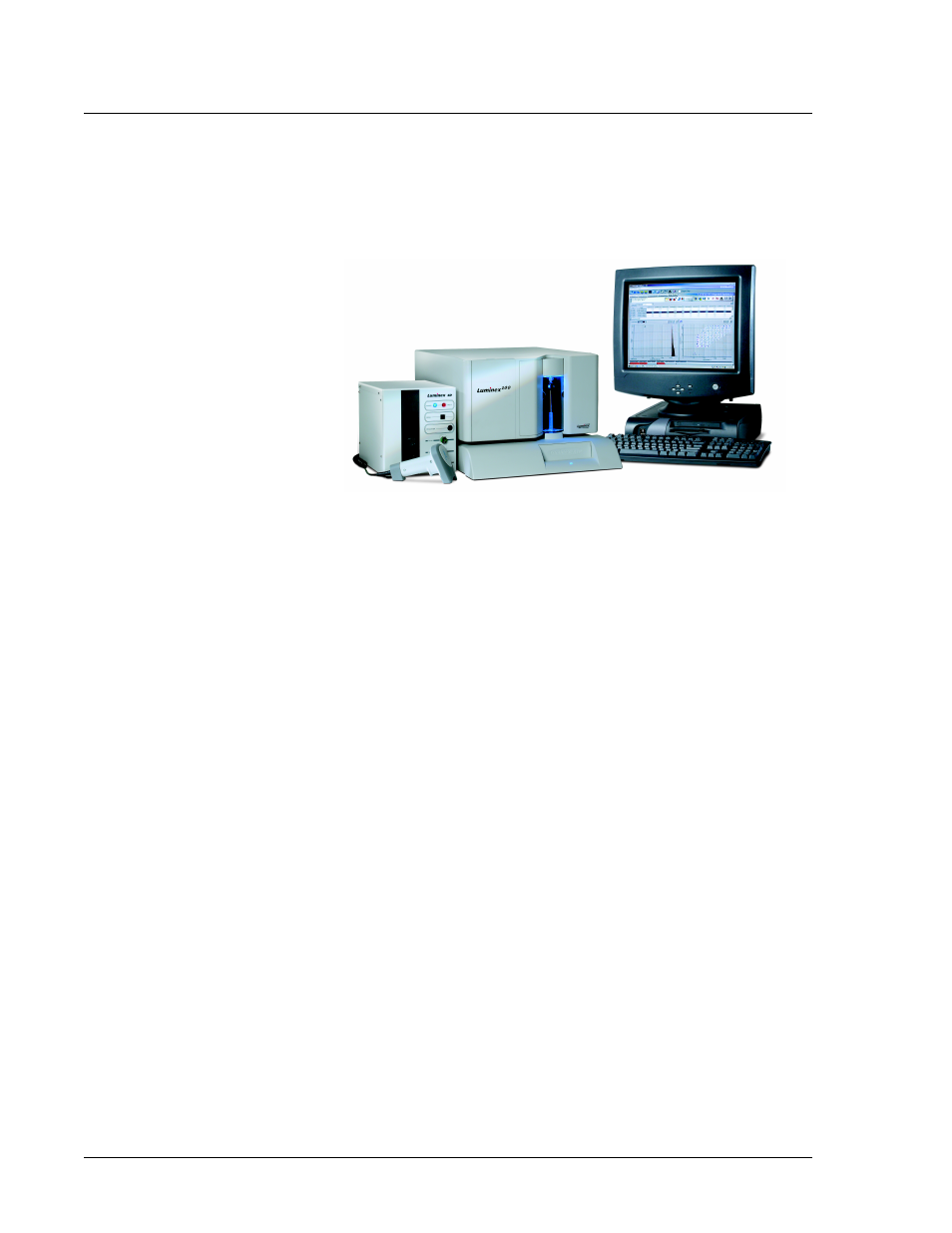
The system consists of three subsystems: electronic, fluidic, and
optical. The following section describes the user-accessible
components of each subsystem. See Figure 1.
Figure 1. Luminex 100 IS 2.2 System
Electronics
Power Input
Module
The power input module contains the Luminex 100 analyzer on/off
switch and fuses.
P1
Communications
Port (SB9-PIN)
Used to connect the Luminex 100 analyzer or the Luminex XYP
instrument to the computer.
Luminex 100
Analyzer
Ventilation Filter
Located on the bottom of the Luminex 100 analyzer, the filter must
be checked and cleaned as necessary. For proper ventilation, do not
obstruct the area below and allow at least two inches (5 cm) of
clearance around the Luminex 100 analyzer.