Interface connector – AMETEK ReFlex User Manual
Page 78
ReFlex Power™
ReFlex Power™ Controller
M380056-01 Rev J
3-15
I
NTERFACE
C
ONNECTOR
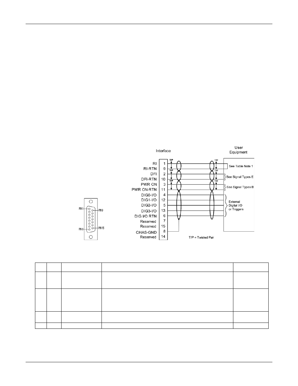
Provides user access to programmable digital I/O and ReFlex Power™
monitoring signals.
Connector: 15-pin D-SUB
Positronic Connector P/N SD15M1000Z, crimp male,
AMETEK P/N 856-918-15
Crimp contacts: Positronic Industries P/N MC7520D (initially
supplied with connector)
Backshell: Positronic P/N D15000Z00, AMETEK P/N 856-975-16
Wire size: Recommended 22 AWG (max 20 AWG)
length: maximum 10 meters (can be extended subject to the
environment, cable type, and interface circuits).
Recommend twisted shielded cables.
Figure 3-4. Interface Connector, Front Panel View, and Interface Connector Wiring Diagram
Table 3-1. Control Connector Pinout
Pin Type
Signal
Function
Signal Level
1
A
RI
(Remote Inhibit)
1
Active-High input signal that is utilized to inhibit all power
module outputs (Pulled High internally). Low input (or
connection between Pins 1 & 9) will enable all outputs.
TTL
2
E
DFI
(Discrete Fault Indicator) Active-High output signal that
indicates events/faults within system modules; derived from
open collector of floating opto-isolator. External pull-up
resistor required.
TTL
3
B
PWR ON
Normally-open relay contacts that close when the ReFlex
Power™ Controller power is on
Relay Closure
4
A
DIG0-I/O
Input/Output: programmable digital I/O
TTL