Interface pinout, Optional interface connector accessories, Dc input connector – AMETEK ReFlex User Manual
Page 295
Active Loads
ReFlex Power™
7-20
M380056-01 Rev J
I
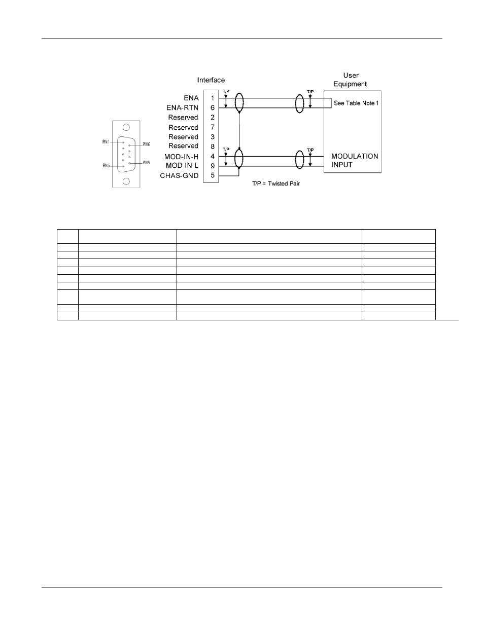
NTERFACE PINOUT
Figure 7-6. Interface Connector, Front Panel View, and Wiring Diagram
Table 7-2. Interface Connector Pinout
Pin
Name
Function
Signal Level
1
ENA
1
Input: module output enable
TTL logic level
6
ENA-RTN
1
Input: return for ENA signal; connected to Pin-7/8
Signal common
2
Reserved
7
Reserved
3
Reserved
8
Reserved
4
MOD-IN-H
Input: external modulation signal; differential input with
MOD_IN_L
5V/10V analog signal
9
MOD-IN-L
Input: return for external modulation signal, MOD_IN_H
5V/10V analog signal
5
CHAS-GND
Shield ground
Chassis ground
1
Enable signal is internally pulled up to +5 V with a 10 K resistor. To enable the module, the signal is pulled low (<= 0.5 V) with respect to the
ENA RTN signal; this may also be accomplished by shorting Pin 1 to Pin 6.
O
PTIONAL
I
NTERFACE
C
ONNECTOR
A
CCESSORIES
•
AMETEK P/N 5380508-01, 9-pin Loop-back Connector Assembly. Includes a jumper wire between
Pins 1 and 6 to enable the module outputs.
•
AMETEK P/N 5380443-01, Power Module, 9ft. Unterminated Interface Cable Assembly. Use when
interfacing to an external system.
•
AMETEK P/N 5380443-03, Power Module, Right Angle, 9ft. Unterminated Interface Cable
Assembly. Use when interfacing to an external system.
DC
I
NPUT
C
ONNECTOR
The DC Input connector (Figure 7-7) provides terminations for the input
and remote sense connections to the load (see Table 7-3 for pinouts).
Connector: MIL P/N MS3106F-20-24S, AMETEK P/N 855-363-08
Backshell: Included with connector.
Wire size: see Table 7-3.
Twisted cable recommended, 25uH max. wire inductance