7 ac/dc input disconnect device, Ac/dc – AMETEK ReFlex User Manual
Page 52
ReFlex Power™
Mainframe
M380056-01 Rev J
2-17
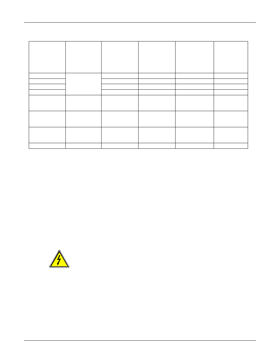
Table 2-3. Mainframe Input Current Demand
Input Service
Input Service
Connection
Maximum
Input Service
Line Current
Maximum
Mainframe
Input
Connector
Line Current
Maximum
Aggregate
Output Power
per Mainframe
Maximum
Output
Power per
Slot Group:
Slots 1-4,
4-8, and 8-12
100V
1-phase
24A
24A
5kW
1.7kW
115/120V
24/23A
24/23A
6kW
2kW
200/208V
14/13.5A
14/13.5A
6kW
2kW
220/230/240V
13/12.4/11.9A
13/12.4/11.9A
6kW
2kW
200V or 208V
3-phase, delta
3-wire, plus
ground
24.3A or 23.4A
14A or 13.5A
6kW
2kW
115/200V or
120/208V
3-phase, wye
4-wire, plus
ground
24A or 23A
24A or 23A
6kW
2kW
220/380V,
230/400V, or
240/415V
3-phase, wye
4-wire, plus
ground
13/12.4/11.8A
13/12.4/11.9A
6kW
2kW
270VDC
DC
12A at 210VDC 12A at 210VDC 6kW
2kW
2.4.7
AC/DC
I
NPUT
D
ISCONNECT
D
EVICE
The ReFlex Power™ system does not have any means to disconnect it from the
AC/DC input service. The front panel POWER switch of the Controller module in
the Mainframe does not disconnect the AC/DC input line from the modules or
Mainframe. Ensure that a suitable disconnecting device is incorporated into the
system installation, so that isolation will be provided when it is opened. The
switch or circuit breaker must be located close to the ReFlex Power™ system,
within reach of the operator, and clearly labeled as the disconnection device. In
multi-Mainframe systems, each Mainframe has an independent AC/DC input, so
the input disconnect device should simultaneously open/close the input
connection to all assets comprising the system.
WARNING
To prevent a shock hazard, ensure that the AC/DC input
disconnect device is open, and that the safety ground
conductor is connected to the rear panel ground stud,
before inserting/removing modules into/from the Mainframe.
The Mainframe backplane input power distribution remains
energized whenever the AC/DC input is connected.