J3 analog control out – AMETEK ReFlex User Manual
Page 60
ReFlex Power™
Mainframe
M380056-01 Rev J
2-25
J3
A
NALOG
C
ONTROL
O
UT
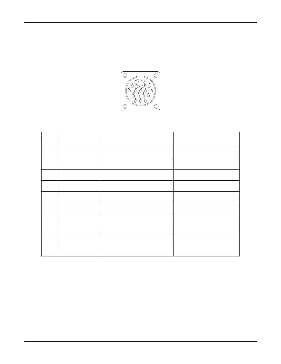
Refer to Figure 2-10 for a view of the ANALOG CTRL OUT, J3, connector.
The pinout and functions of the connector are presented in Table 2-8. The
associated maximum wire gauge for connector terminations, and
recommended maximum wire lengths are presented in Table 2-10.
Figure 2-10. J3 Analog Control Output Connector, Mainframe Rear Panel View
Table 2-8. J3 ANALOG CTRL OUT Connector Pinout
Pin
Name
Function
Signal Level
F
SYNCH-OUT
Input/output: SYNC bus
differential signal with SYNC-L
RS-485 logic levels
referenced to module AGND
R
SYNCL-OUT
Input/output: SYNC bus
differential signal with SYNC-H
RS-485 logic levels
referenced to module AGND
U
CURRH-OUT
Input/output: CURR bus
differential signal with CURR-L
10V analog signal referenced
to module AGND
N
CURRL-OUT
Input/output: CURR bus
differential signal with CURR-H
10V analog signal referenced
to module AGND
S
CMDH-OUT
Output: CMD bus differential
signal with CMD-L
10V analog signal referenced
to module AGND
H
CMDL-OUT
Output: CMD bus differential
signal with CMD-H
10V analog signal referenced
to module AGND
K
/FLTBUS-OUT
Input/Output: summary fault
signal bus
5V digital signal referenced to
module AGND
T
AGND-OUT
Analog signal reference
Module circuit common
AGND referenced to output
return (negative) terminal
J
CHAS-GND
Chassis ground
Chassis
A,C,
D,G,
H,I,K,
L, M
-
Reserved
-