AMETEK ReFlex User Manual
Page 184

ReFlex Power™
Fixed Power DC Power Supply
M380056-01 Rev J
5-15
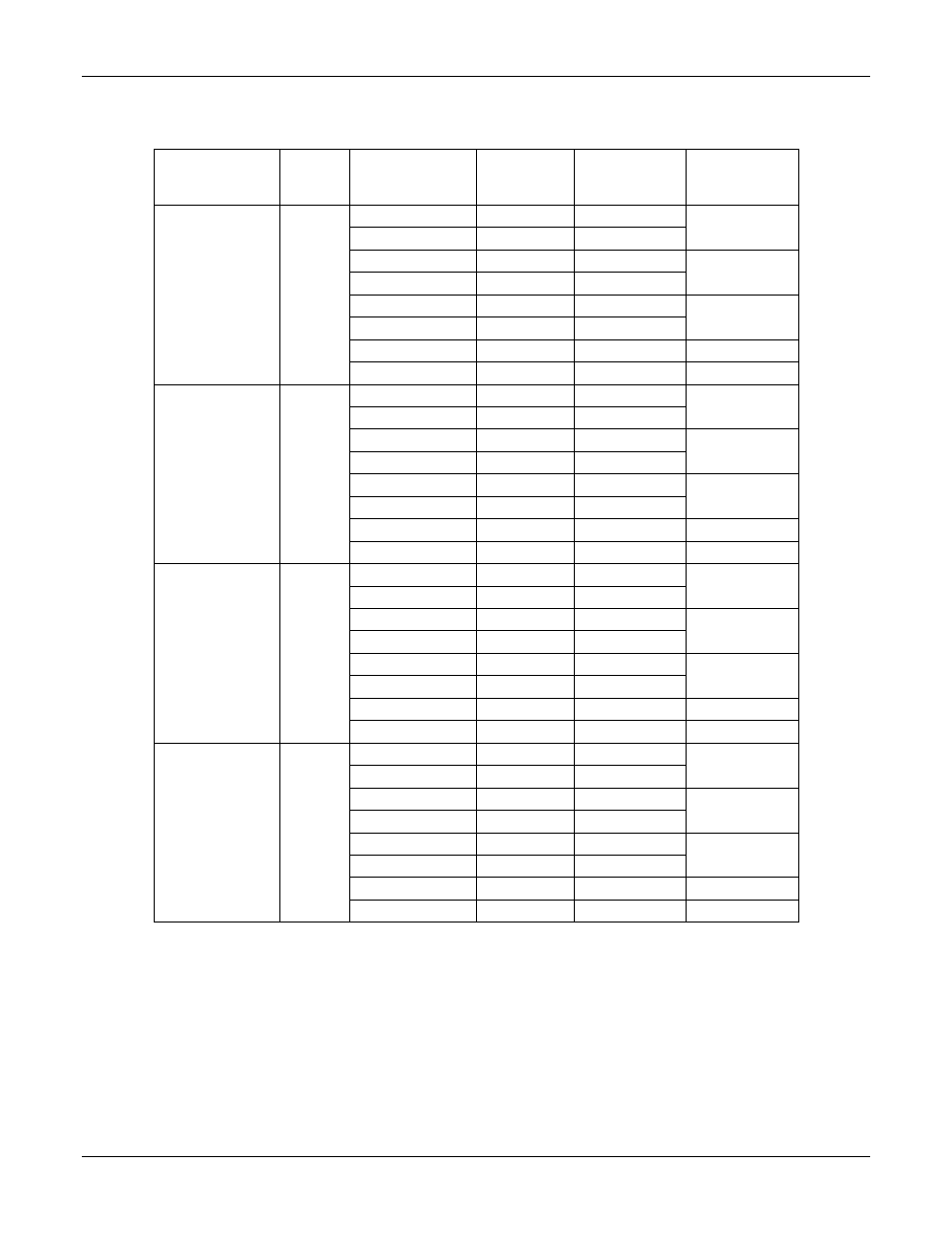
Table 5-1. Mainframe Connector and Power Allocation Information
Input
Service
Phases
Input
Designation
Input
Connector
Pin
Input Service
Connection
Slot
Supplied
100/115/120VAC
200/208VAC
220/230/240VAC
1
L1
F
Phase
Slot 1-4
L1-RTN
E
Return
L2
A
Phase
Slot 5-8
L2-RTN
G
Return
L3
B
Phase
Slot 9-12
L3-RTN
C
Return
GND
D
Ground
Slot 1-12
Safety GND
Chassis GND
Ground
Chassis
200/208VAC
3
Delta
L1
F
Phase-A
Slot 1-4
L1-RTN
E
Phase-B
L2
A
Phase-B
Slot 5-8
L2-RTN
G
Phase-C
L3
B
Phase-C
Slot 9-12
L3-RTN
C
Phase-A
GND
D
Ground
Slot 1-12
Safety GND
Chassis GND
Ground
Chassis
200/208VAC
220/230/240VAC
3
Wye
L1
F
Phase-A
Slot 1-4
L1-RTN
E
Neutral
L2
A
Phase-B
Slot 5-8
L2-RTN
G
Neutral
L3
B
Phase-C
Slot 9-12
L3-RTN
C
Neutral
GND
D
Ground
Slot 1-12
Safety GND
Chassis GND
Ground
Chassis
210-360VDC
DC
L1
F
Source
Slot 1-4
L1-RTN
E
Return
L2
A
Source
Slot 5-8
L2-RTN
G
Return
L3
B
Source
Slot 9-12
L3-RTN
C
Return
GND
D
Ground
Slot 1-12
Safety GND
Chassis GND
Ground
Chassis
A plug/socket connector is provided on the rear panel of the Mainframe for
connecting the unit to the AC/DCpower source. The connector also provides a
safety ground termination. The input power cable should include a safety ground
wire to connect the chassis of the Mainframe to the safety ground of the AC/DC
power source. Since the AC input leakage current could exceed 3.5mA, a second
