2 controls and indicators – AMETEK ReFlex User Manual
Page 250

ReFlex Power™
DC Power Supplies
M380056-01 Rev K
6-47
6.5.2
C
ONTROLS AND
I
NDICATORS
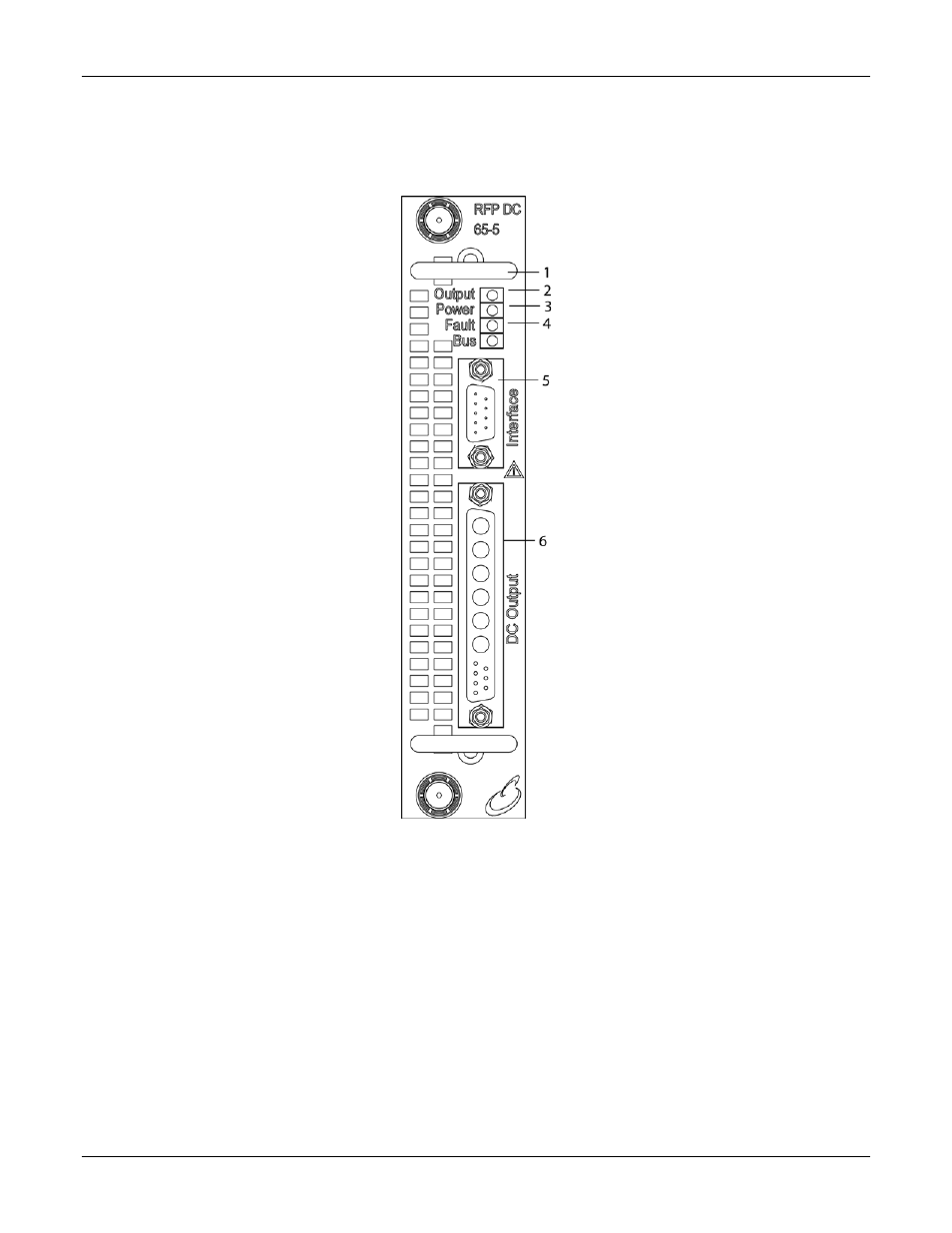
Figure 6-17 shows the connectors and indicators of a typical DC module front
panel, followed by a description.
Figure 6-17. Programmable DC Module Front Panel (RFP-D1065-5A1-XXXX shown)
1 –OUTPUT Indicator: Green LED lights when output voltages are enabled or isolation
relays are closed
2 – POWER Indicator: Green LED lights when AC/DC input power is applied to the module.
3 – FAULT Indicator: Red LED lights when an abnormal internal operating condition has
been detected; the output would be disabled and the isolation relay opened.
4 – BUS Indicator: Green LED lights when internal inter-module communications has been
established.
5 – INTERFACE connector for remote isolated digital signals.
6 – DC OUTPUT connector for the output voltages and remote sense.
