Interface connector – AMETEK ReFlex User Manual
Page 110

ReFlex Power™
AC Power Supplies
M380056-01 Rev K
4-25
I
NTERFACE
C
ONNECTOR
The Interface connector provides terminations for external connections to
digital and analog control signals.
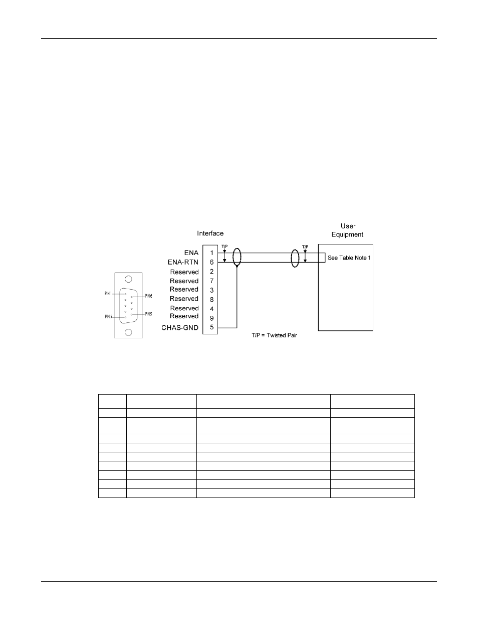
Refer to Figure 4-7 for a view of the connector showing pin numbers. The
pinout and functions of the connector signals are presented in Table 4-3.
Connector: Positronic Industries P/N SD9M1000Z, AMETEK P/N 856-214-09
Crimp contacts: Positronic Industries P/N MC7520D (initially supplied with connector)
Backshell: Positronic Industries P/N D9000Z00, AMETEK P/N 856-247-10
Wire size:
Maximum gauge 20 AWG (recommended)
Length: maximum 10 meters (can be extended subject to the
environment, cable type, and interface circuits).
Figure 4-7. Interface Connector, Front Panel View, and Wiring Diagram
Table 4-3. Interface Connector Pinout
Pin
Name
Function
Signal Level
1
ENA
1
Input: module output enable
TTL logic level
6
ENA-RTN
1
Input: return for ENA signal; connected to
Pin-7/8
Signal common
2
Reserved
7
Reserved
3
Reserved
8
Reserved
4
Reserved
9
Reserved
5
CHAS-GND
Shield ground
Chassis ground
1
Enable signal is internally pulled up to +5 V with a 10 K resistor. To enable the module, the signal is pulled low
(<= 0.5 V) with respect to the ENA RTN signal; this may also be accomplished by shorting Pin 1 to Pin 6.
