Parallel configuration – AMETEK ReFlex User Manual
Page 255

DC Power Supplies
ReFlex Power™
6-52
M380056-01 Rev K
(-)
(-)
(-)
(+)
(+)
(+)
Output
Sense
Input
Load
Power Supply
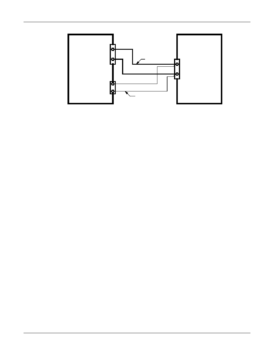
Twisted-Pair Cable
Twisted-Pair Cable
(shielded if noise present)
Figure 6-19. Standalone Output Configuration
P
ARALLEL
C
ONFIGURATION
DC power supply modules of the same model can be connected in parallel.
The paralleled supplies operate in a master/slave configuration, where the
master controls the output voltage and total current, and provides control
signals through the Mainframe backplane to the slaves to set their output
current. The routing of signals in this interface requires that parallel modules
must be located in a contiguous physical group; no intervening modules
(which are not part of the parallel group) are allowed to be located within the
parallel group. Individual modules of the group can be separated by empty
slots, and the group can be extended between two Mainframes.
The outputs of the modules must be hardwired externally, while all internal
control signal connections are done automatically when the parallel group is
set up through software. The remote sense leads are connected only to the
master module. Figure 6-20 shows a parallel connection of two units with
remote sensing.
The paralleled modules are programmed as a single, virtual channel with a
current rating equal to the sum of the number of modules connected in
parallel. The master and slave supplies will share the output current equally.
Fault shutdown is coordinated across all modules: a fault within any module
of the group will result in shutdown of all modules. The parallel master will be
the module that has the lowest slot number in the parallel group.
