5 output voltage line plus load regulation, 6 output voltage ripple and noise, 7 voltage on/off sequencing – AMETEK ReFlex User Manual
Page 203
Fixed Power DC Power Supply
ReFlex Power™
5-34
M380056-01 Rev J
5.7.5
O
UTPUT
V
OLTAGE
L
INE
P
LUS
L
OAD
R
EGULATION
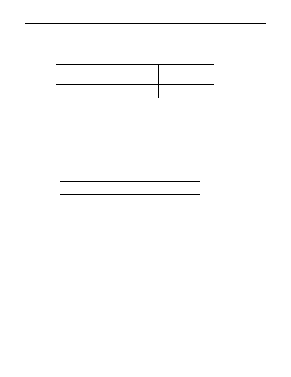
Table 5-8 lists the output voltages under both line and load regulation extremes.
Table 5-8. Line and Load Regulation
Output
Minimum
Maximum
+5VDC
+ 4.848
+ 5.072
-5VDC
- 4.848
- 5.072
+15VDC
+14.650
+ 15.350
-15VDC
- 14.650
- 15.350
5.7.6
O
UTPUT
V
OLTAGE
R
IPPLE AND
N
OISE
The output voltage ripple and noise specification is listed in the table below. Use
the DSO and limit the bandwidth to 20 MHz for all measurements. Also, the
scope connections must be made as close as possible to the FPDC output
terminals. Excessive lead lengths including the probes ground will cause
erroneous measurements.
Table 5-9. Ripple and Noise
Output
Ripple and Noise
(peak-peak)
+5VDC
150 mV
-5VDC
80 mV
+15VDC
150 mV
-15VDC
150 mV
5.7.7
V
OLTAGE
O
N
/O
FF
S
EQUENCING
The turn on sequence is measured using all 4 channels of the DSO. For turn on,
trigger the DSO from either the +15 or –15 connections and observe the other
three voltages. The +15VDC and –15VDC turn on first and essentially at the
same time. The +5VDC turns on next and shall not start to turn on until the
+15VDC and –15VDC have reached at least 50% of their output level. The –
5VDC turns on last.
The –5VDC turns off first and hence should be used as the trigger for capturing
the turn off sequence. The +5VDC turns off after the –5VDC. The +15VDC and –
15VDC outputs turn off last and shall not start off until the +5VDC has reached
0.5V or less.