Series configuration – AMETEK ReFlex User Manual
Page 256

ReFlex Power™
DC Power Supplies
M380056-01 Rev K
6-53
CAUTION
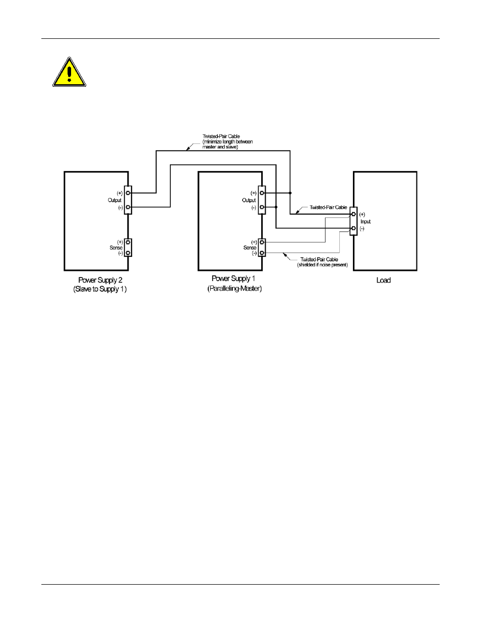
The outputs of paralleled modules must be wired in parallel at the front
panel output terminals of the units. Use the shortest practical cable length.
Operation of a paralleled module with its return (negative) terminal not
connected to the load could result in damage to the module.
Figure 6-20. Parallel Output Configuration
S
ERIES
C
ONFIGURATION
Multiple modules of the same model can be connected in series to obtain a
higher output voltage, within the limits of the float voltage specification. The
series master is the module with the lowest slot number in the group of
modules that are connected together. The supplies are interconnected with
the negative terminal of one supply being connected to the positive terminal
of other. The output voltage is derived from the positive and negative
terminals of the total string.
The series group does not utilize the analog control signals of the backplane;
therefore, it is not restricted by contiguous physical location, as in a parallel
group. The outputs of the modules must be hardwired externally, while all
internal control signal connections are done automatically when the series
group is set up through software. In order not to compromise the load
regulation of the output voltage, the series connection of the remote sense
leads must be made to single points, and must not have any intervening load
wiring. Figure 6-21 shows the series connection of three units with remote
sensing.
