Wire voltage drop – AMETEK ReFlex User Manual
Page 191
Fixed Power DC Power Supply
ReFlex Power™
5-22
M380056-01 Rev J
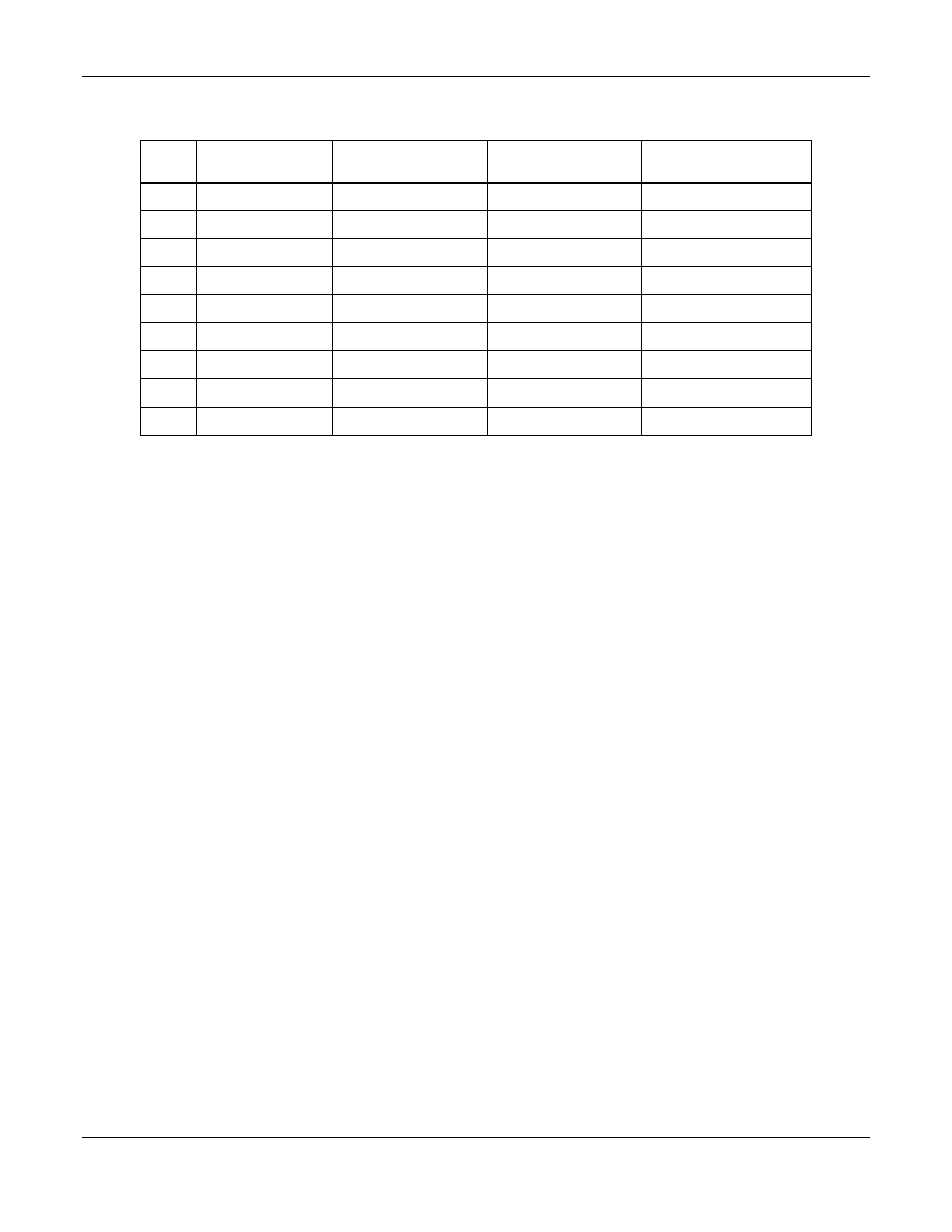
Table 5-4. Wire Data
AWG
Copper Area,
cm
2
Resistance,
Ω/m at 20°C
Resistance,
Ω/m at 100°C
Current Rating,
A for 30ºC Rise
6
0.133
0.0013
0.0017
54
8
0.0837
0.0021
0.0028
40
10
0.0526
0.0033
0.0044
27
12
0.0331
0.0052
0.0069
21
14
0.0208
0.0083
0.011
16
16
0.0131
0.0132
0.0174
12
18
0.00823
0.0209
0.0276
10
20
0.00518
0.0333
0.044
7.5
22
0.00326
0.053
0.07
5.5
W
IRE
V
OLTAGE
D
ROP
For applications where regulation is important, the contribution of the load
wiring to voltage drop from the output terminals of the FPDC module to the load
must be considered. The wire gauge must be selected to maintain an
acceptable total voltage drop for the load wiring under the maximum peak
current. The resistance of the load wiring must be determined for the sum total
length of the output lead and the return lead. The total voltage drop is the sum
of the individual drops in the output and return leads. Table 5-4 gives the
resistance per meter (m) of various wire gauges at 20 °C and 100 °C.
Use the following equation to calculate the resistance for other wire
temperatures:
R = R20°C x [1 + 0.004 x (T - 20°C)]
where,
R = resistance,
Ω/m, at temperature T
R20°C = resistance,
Ω/m, at 20°C
T = temperature of wire, °C