Mainframe interconnect connectors – AMETEK ReFlex User Manual
Page 55
Mainframe
ReFlex Power™
2-20
M380056-01 Rev J
Item
AMETEK
Part No.
Description
Qty
Manufacturer Part
No.
Manufacturer
Suggested Source(s)
1
855-130-02
Conn, 7P, 8AWG,
Plug, P-Earth, S
1
DL3106A24-10S
Amphenol
Arrow Electronics:
Newark:
2
855-16A-X3
Conn, Cable Clamp,
SS 24/28 w/Bushing
1
M85049/41-16A, or
MS3057-16A
ITT Cannon, Amphenol /
Bendix
PEI-Genesis:
3
890-887-07
Cable, 10AWG X
7W, 600V, 80C
2m 87707
Alpha Wire & Cable
Alpha Wire Company:
Industrial Electric Wire & Cable:
WARNING
A separate, dedicated safety ground wire must be connected to the
Mainframe rear panel safety ground stud. Operating the ReFlex Power™
system with the safety ground wire disconnected could result in a shock
hazard.
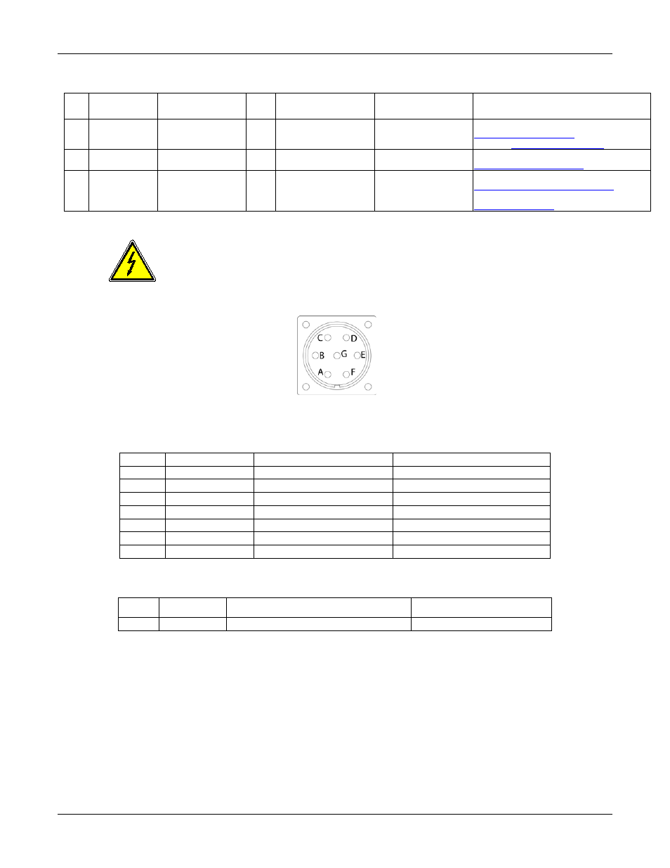
Figure 2-7. J5 AC/DC Input Connector, Mainframe Rear Panel View
Table 2-4. J5 AC/DC Input Connector Pinout
Pin
Name
Function
Signal Level
F
L1
Input: line-1
90-264VAC; 210-300VDC
E
L1-RTN
Input: return for line-1
90-264VAC; 210-300VDC
A
L2
Input: line-2
90-264VAC; 210-300VDC
G
L2-RTN
Input: return for line-2
90-264VAC; 210-300VDC
B
L3
Input: line-3
90-264VAC; 210-300VDC
C
L3-RTN
Input: return for line-3
90-264VAC; 210-300VDC
D
CHAS-GND
Safety ground
Chassis ground
Table 2-5. GND, Safety Ground Stud
Pin
Name
Function
Signal Level
E1
GND
Chassis safety ground; 8-32 stud
Chassis ground
M
AINFRAME
I
NTERCONNECT
C
ONNECTORS
The digital control connectors, DIGITAL CTRL IN (J2) and DIGITAL CTRL
OUT (J1), and the analog control connectors, ANALOG CTRL IN (J4) and
ANALOG CTRL OUT (J3), provide a signal interface for multi-Mainframe
ReFlex Power™ systems, connected in a daisy-chain manner. J1 and J3 are