Part 1 specification – IAI America REXT User Manual
Page 99
S
P
*
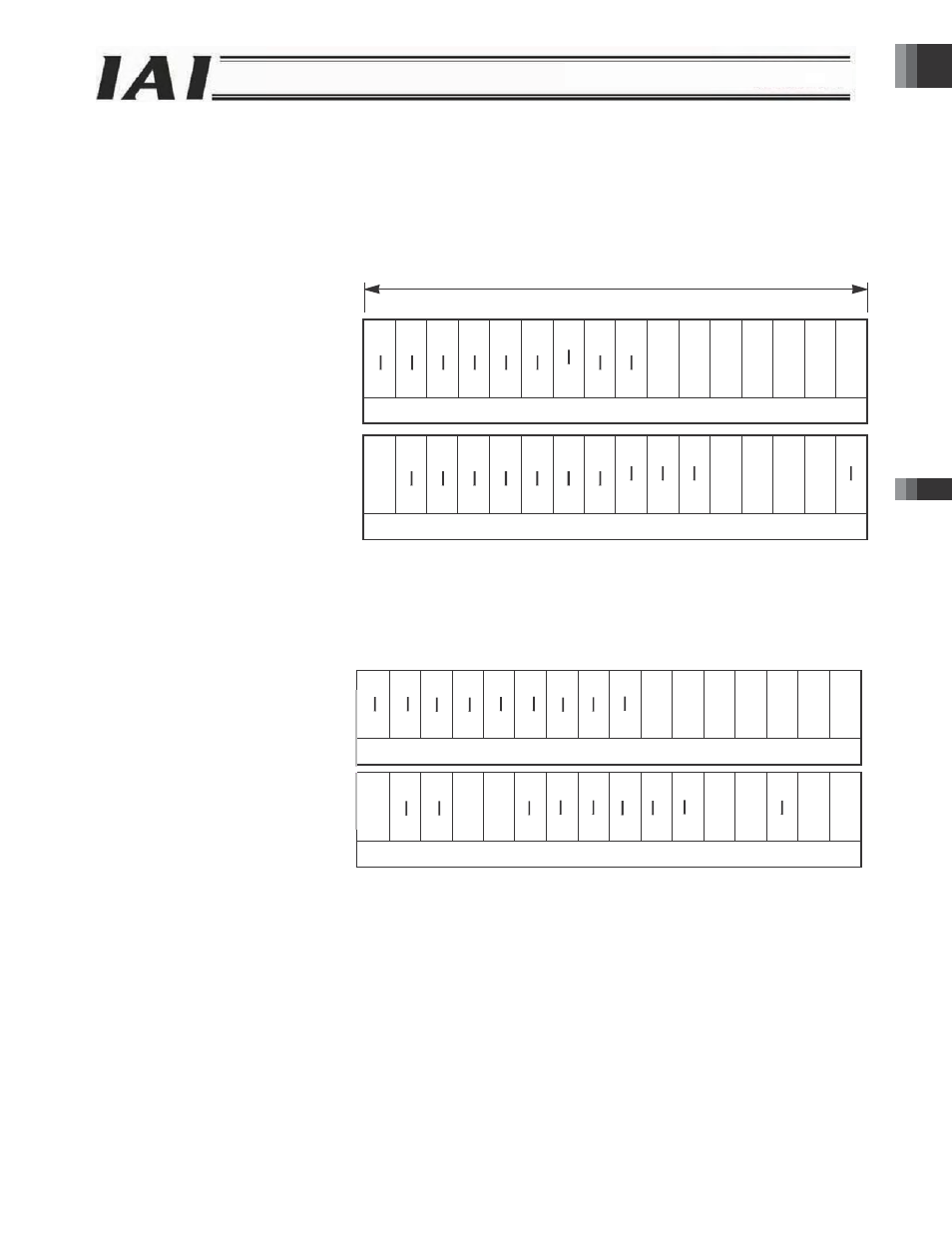
3.7.8 Sig
Signal assignm
PLC output = A
LC input = Axis
* m indicates t
n indicates th
Word addres
RS485SIO
networks.
CC‐Link
RWw (m + 0
RWw (m +1
CC‐Link
RWr (m +
RWr (m +
gnal Assign
ments in soleno
Axis control sig
s status signal
he first register
he relative addr
sses are used f
DeviceNet
Address*
0) n +0
1) n + 1
DeviceNet
Address*
0) n +0
1) n + 1
ments in So
oid valve mode
gnal
r address of ea
ress at the beg
for CC-Link and
(Lower byte)
n + 0
(Upper byte)
n + 1
n + 2
n + 3
PROFIBUS
EtherNet/IP
RS485SIO
(Lower byte)
n + 0
(Upper byte)
n + 1
n + 2
n + 3
PROFIBUS
EtherNet/IP
RS485SIO
BKR
L
EMG
S
olenoid Val
1 are shown b
b15
b14 b1
b15 b14 b13
ach axis.
ginning of each
d DeviceNet ne
C
C
ZON
E
1
PZO
N
E
ve Mode 1
below.
3 b12 b11
b1
b12
b11
b1
axis.
etworks, while
Completed pos
Command posi
Control
Status
1 word =
10
b9
b8
b
10 b9
b8
b
byte addresses
PE6
PE5
sition number
ST6
ST5
ition number
signal
signal
16 bits
b7
b6
b5
b7 b6
b5
b
s are used for
PE4
PE3
PE2
ST4
ST3
ST2
SON
RES
STP
SV
ALM
b4
b3
b2
b4
b3
b2
Profibus, Ethe
PE1
PE0
ST1
ST0
HOME
HEN
D
PEN
D
b1
b0
b1
b0
rNet/IP and
Part 1 Specification
Chap
ter 3 G
a
tew
ay R u
n
it
Part 1 Specification
-99-