Part 1 specification – IAI America REXT User Manual
Page 187
Part 1 Specification
Chapter 3 Gateway R unit
163
Part 1 Specification
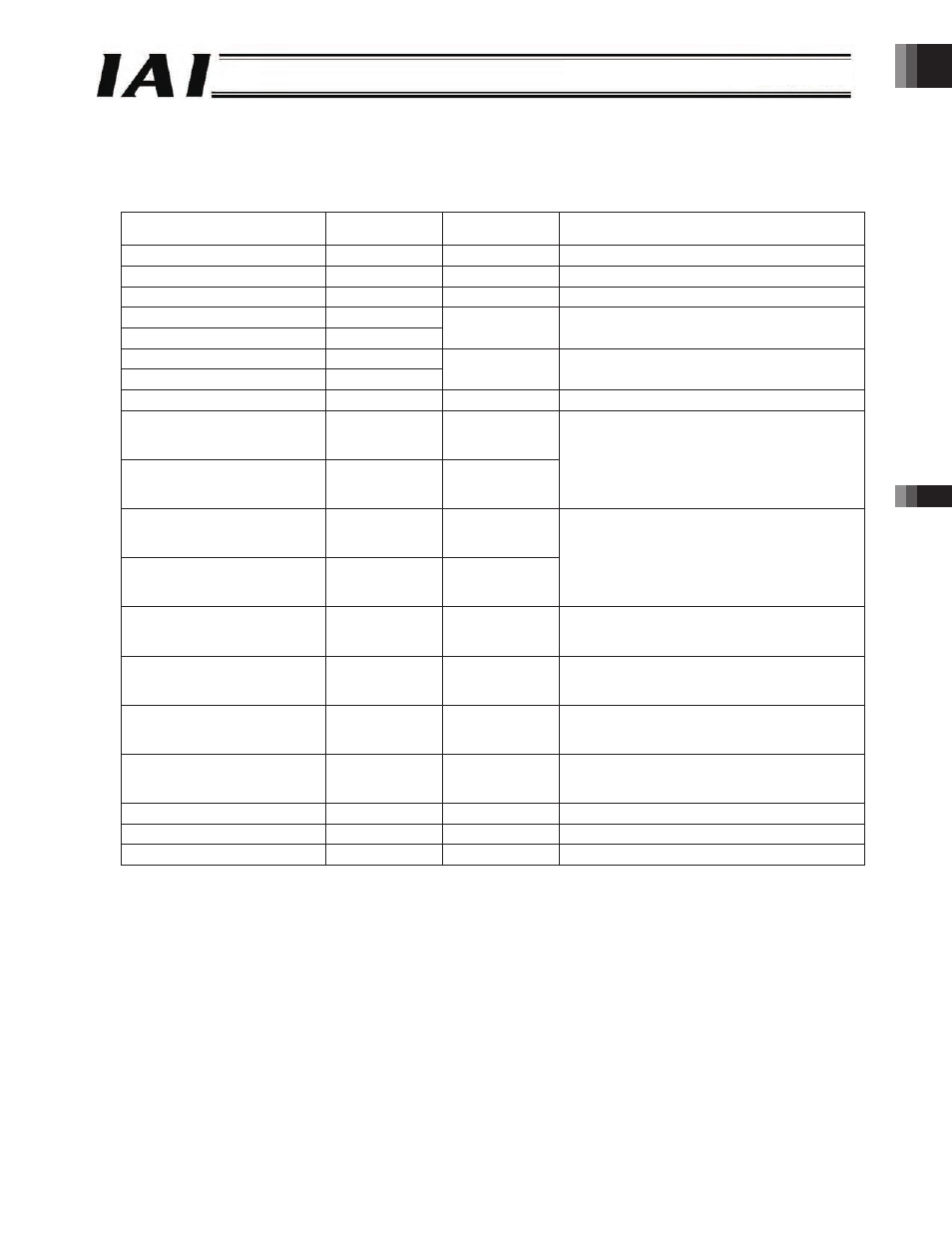
[4] Query format for push operation
Write all data required for axis operation (position, positioning band, speed, acceleration/deceleration, push-current
limiting value) to the registers.
z
Query (Position data change)
Field name
RTU mode data
(8 bits)
Data length
(bytes)
Remarks
Header
None
-
Slave address
3F H
1
Fixed.
Function code
10 H
1
Starting address
(upper)
F6 H
Starting address
(lower)
0C H
2
Initial control signal register address of axis (1)
Number of registers
(upper)
00 H
Number of registers
(lower)
08 H
2
The number of registers is “8” corresponding to
new data 1 to 8.
Bytes
10 H
1
Number of registers x 2 = 16 (10H)
New data 1
(upper)
36 H
New data 1
(lower)
B0 H
1 each for upper
and lower words
2
New data 2
(upper)
00 H
New data 2
(lower)
00 H
1 each for upper
and lower words
2
Position data specification
140.00 mm = 14000 = 000036B0 H
New data 3
(upper)
01 H
New data 3
(lower)
F4 H
1 each for upper
and lower words
2
New data 4
(upper)
00 H
New data 4
(upper)
00 H
1 each for upper
and lower words
2
Positioning Band
5.0 mm = 500 = 01F4 H
New data 5
(upper)
00 H
New data 5
(upper)
32 H
1 each for upper
and lower words
2
Speed
50 mm/sec = 50 = 0032 H
New data 6
(upper)
00 H
New data 6
(upper)
1E H
1 each for upper
and lower words
2
Acceleration/deceleration
0.30 G = 30 = 001E H
New data 7
(upper)
00 H
New data 7
(upper)
7F H
1 each for upper
and lower words
2
Push-current limiting value
0% = 007F H
New data 8
(upper)
30 H
New data 8
(upper)
11 H
1 each for upper
and lower words
2
Control signal
Set DIR, PUSH and CSTR to “1.”
Error check
(CRC)
16 bits
2
Based on calculation result
Trailer
None
-
Total bytes
Sent Query:
3F10F60C00081036B0000001F40000
0032001E007F30118287
Received Response: 3F10F60C0008369A
-187-