Part specification, Gateway control/status signals – IAI America REXT User Manual
Page 72
0
Part 1 Specification
Chapter 3 Gateway R unit
0
Part Specification
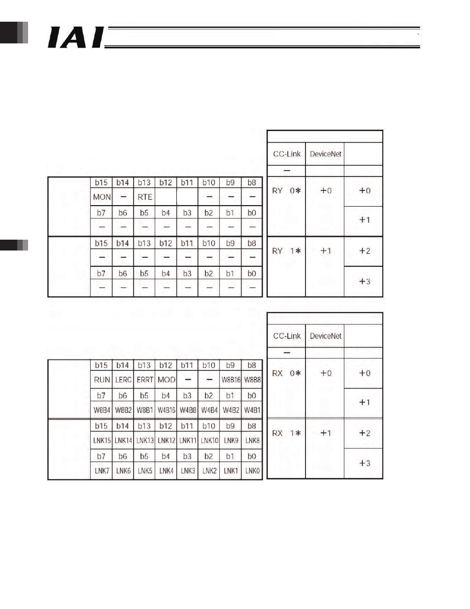
Gateway
control
signal 0
Gateway
control
signal
Relative channel Relative byte
Address*
Relative channel Relative byte
Gateway
status
signal 0
Gateway
status
signal
PLC input
.. Gateway Control/Status Signals
In the address configuration of the Gateway R unit, the first two input words and output words are used to control the Gateway
R unit.
These signals can be used to perform ON/OFF control of ROBONET communication (SIO control) and monitor the
communication status as well as the status of the Gateway R unit.
* Each address is a relative address from the beginning of the gateway.
Word addresses are used by the CC-Link and DeviceNet types, while byte addresses are used by the Profibus and RS
SIO types.
With the CC-Link type, the asterisk (*) in bit register addresses is a value between 0 and F.
With the CC-Link type, b0 to b are indicated as bA to b (due to hexadecimal notation).
With the Profibus and RS SIO types, b to b are indicated as b0 to b (due to use of byte addresses).
PLC output
Address*
RMOD ECE
* Each address is a relative address from the beginning of the gateway.
Word addresses are used by the CC-Link and DeviceNet types, while byte addresses are used by the PROFIBUS,
EtherNet/IP and RS485SIO types.
With the CC-Link type, the asterisk(*) in bit register addresses is a value between 0 and F.
With the CC-Link type, b10 to b15 are indicated as bA to b7(due to hexadecimal notation).
With the PROFIBUS, EtherNet/IP and RS485SIO types, b8 to b15 are indicated as b0 to b7(due to use of byte addresses)
PROFIBUS
EtherNet/IP
RS485SIO
PROFIBUS
EtherNet/IP
RS485SIO
-72-