Part 1 specification, 8 i/o signals, 1 i/o signal timings – IAI America REXT User Manual
Page 103
Part 1 Specification
Chapter 3 Gateway R unit
81
Part 1 Specification
3.8 I/O Signals
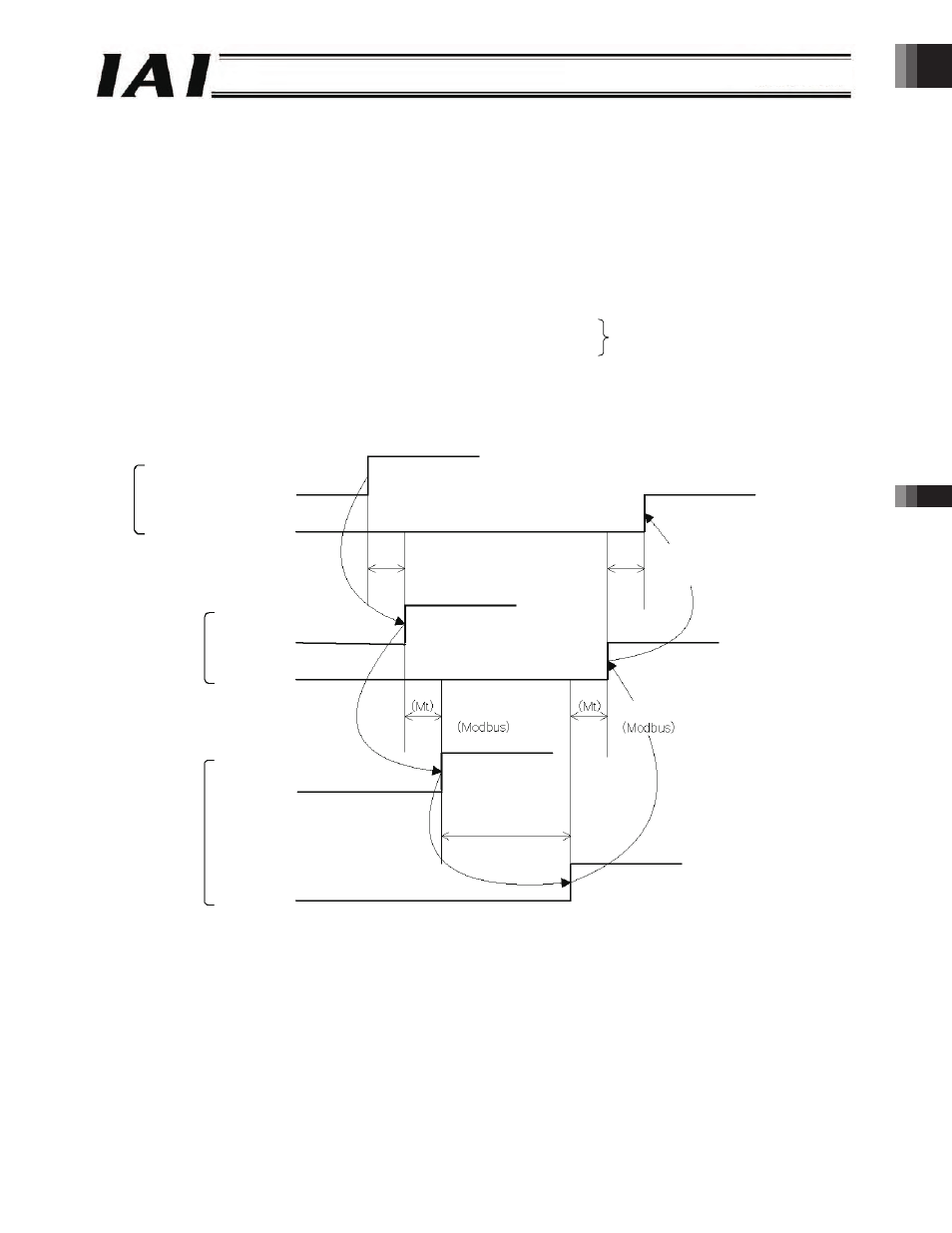
3.8.1 I/O Signal Timings
To operate the ROBO Cylinder using the PLC’s sequence program, a given control signal is turned ON. The maximum
response time after the signal turns ON until the response (status) signal is returned to the PLC is calculated by the formula
below:
Maximum response time (msec) = Yt + Xt + 2 x Mt + Command processing time (operation time, etc.)
Mt = 10 (msec) x (n + 1) : SIO link (Modbus) cycle time
n:
Number of controlled axes
Yt: Master station o remote I/O station transmission delay time
Xt: Remote I/O station o master station transmission delay time
For the master station o remote I/O station transmission delay time (Yt) and remote I/O station o master station transmission
delay time (Xt), refer to the operation manuals of the CC-Link master unit and the PLC installed in the master unit.
(Note) If a communication error occurred due to a problem along the transmission path, etc., communication will be retried
(by up to three times) and consequently the SIO link cycle time (Mt) may become longer than normal.
Field network transmission delay time
PLC sequence program
Control signal
Status signal
Master station o remote I/O station
transmission delay time (Yt)
Remote I/O station o master station
transmission delay time (Xt)
Gateway
Control signal
Status signal
SIO link cycle time
Controller
Control signal
Status signal
SIO link cycle time
Command
processing time
-103-