Part specification – IAI America REXT User Manual
Page 28
Part 1 Specification
Chapter 1 Overview of ROBONET
Part Specification
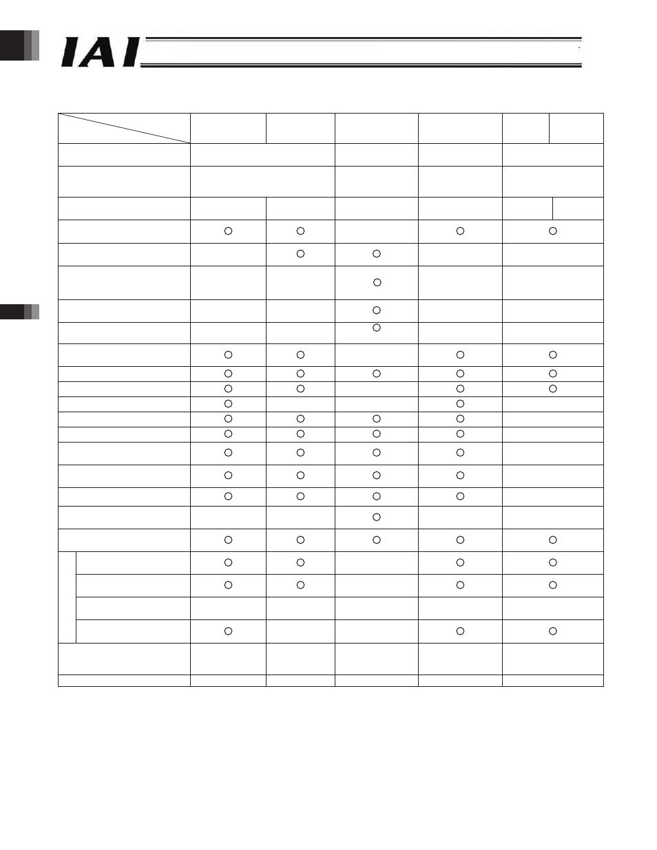
List of ROBONET Operation Functions
Operation mode
Item
Positioner mode Simple direct
mode
Direct numerical
specification mode
Positioner mode
Solenoid
valve
mode
Solenoid
valve mode
Axis area
(both input and output)
words
words
words
words
Fixed area
(both input and output)
words
(The command area can be used.)
words
(The command area
cannot be used.)
words
(The command area
can be used.)
words
(The command area can
be used.)
Number of registrable
positions
points/axis
points/axis
-
points/axis
points/axis
points/axis
Operation by position number
specification
X
Direct position data
specification
X
(Position table)
X
(Position table)
X
(Position table)
Direct speed &
acceleration/deceleration
specification
X
(Position table)
X
(Position table)
*
X
(Position table)
X
(Position table)
Direct positioning band
specification
X
(Position table)
X
(Position table)
X
(Position table)
X
(Position table)
Push operation
X
(Position table)
X
(Position table) (Direct specification)
X
(Position table)
X
(Position table)
Completed position number
monitor
X
Zone output monitor
Position zone output monitor
X
Teaching operation
X
X
X
Jogging operation
X
Inching operation
X
Various status signal monitor
*
X
Current position monitor
*
X
Alarm code monitor *
X
Speed/electrical current
monitor
* *
X
X
X
X
Axis monitor function in
AUTO mode
*
Handshake
X
Position table data
read/write
X
Current position read
X
X
X
X
X
C
omma
nd
Broadcast
X
X
Maximum specifiable position
data value
. mm
(When a
command is used)
. mm
. mm
. mm
(When a command
is used)
. mm
(When a command
is used)
Number of connectable axes
* Various status signals, current position, alarm codes and speed/electrical current can be monitored by accessing each
address of the gateway unit from the PLC.
* Before, axis monitor was not possible in the AUTO mode. This has become possible with the ROBONET, even when the
MODE switch is set to AUTO, by connecting a dedicated touch panel to the TP connector.
* Separate values cannot be set for acceleration and decelerat
* The command is monitored for speed and electrical current.
ion. The acceleration and deceleration are always the same.
-28-