Part 1 specification, 10 field network connector – IAI America REXT User Manual
Page 51
Part 1 Specification
Chapter 3 Gateway R unit
33
Part 1 Specification
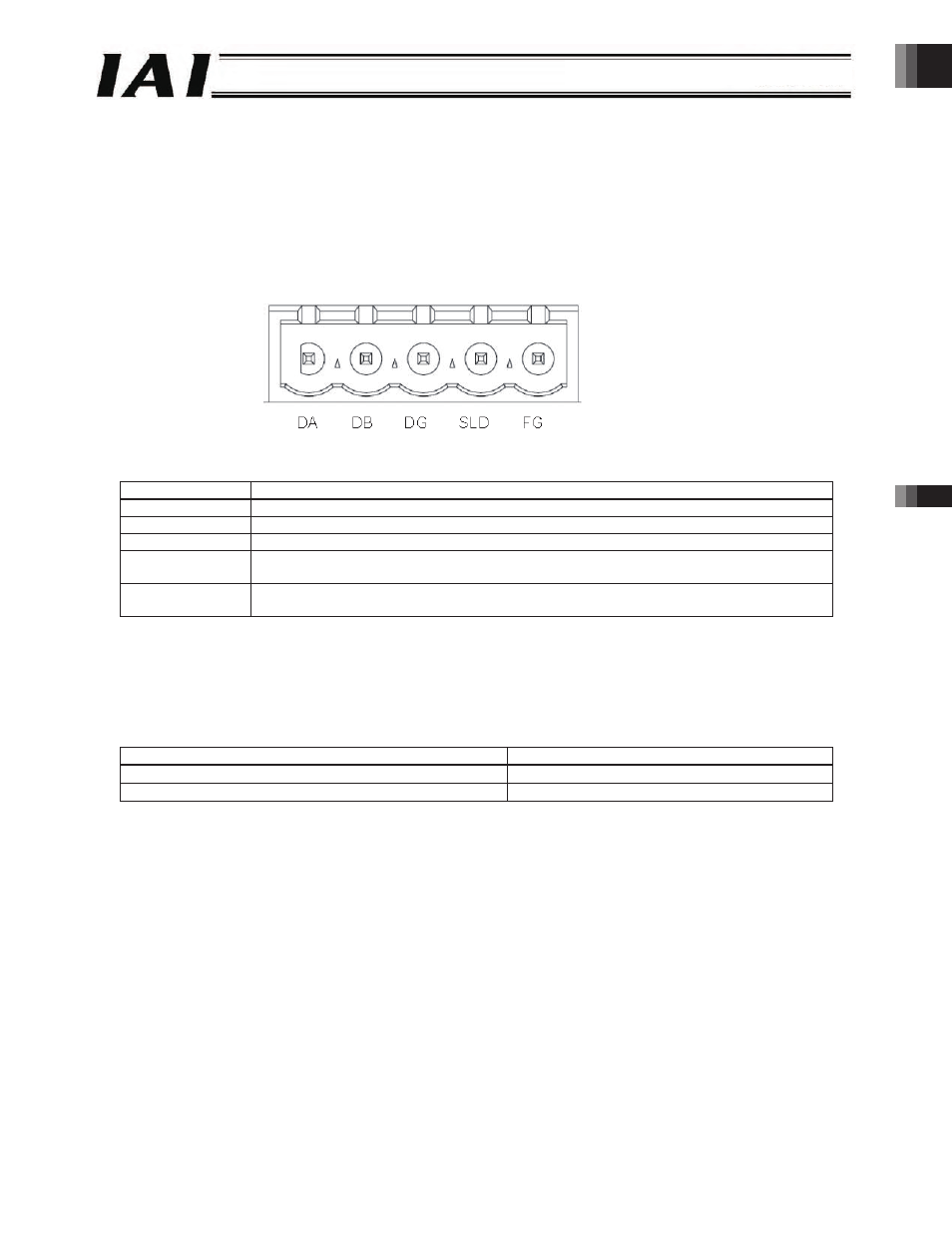
3.5.10 Field Network Connector
This connector is used to connect the master unit of each field network.
The connector varies according to the field network type.
(1) CC-Link (RGW-CC)
RGW-CC-end connector: MSTBA2.5/5-G-5.08AU (by Phoenix Contact)
Cable-end connector:
MSTB2.5/5-ST-5.08ABGYAU (by Phoenix Contact) = Standard accessory
CC-Link communication connector
Signal name
Explanation
DA
Communication line A
DB
Communication line B
DG
Digital ground
SLD
Connect the shield of the shielded cable.
This signal is internally connected to “FG” and the enclosure.
FG
Frame ground
This signal is internally connected to “SLD” and the enclosure.
* The cable-end connector, “terminal resistor 110 :, 1/2 W” and “terminal resistor 130 :, 1/2 W” are supplied.
A terminal resistor must be connected to the units at both ends of the CC-Link system. If the RGW-CC is a terminal unit
of the CC-Link system, connect the supplied terminal resistor between the DA and DB pins of the connector.
The applicable terminal resistor varies according to the type of the CC-Link cable used, as shown below. Use the
terminal resistor appropriate for the cable.
For details, refer to the operation manual of the master unit.
Cable name
Terminal resistor
Dedicated CC-Link cable (Version 1.00, Version 1.10)
110 :, 1/2 W
Dedicated high-performance CC-Link cable (Version 1.00)
130 :, 1/2 W
RGW-CC end
-51-